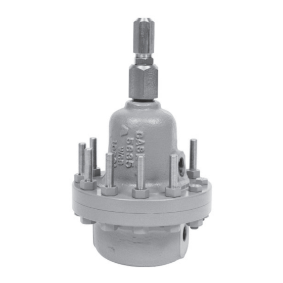
cashco 123-1+6+S Manuale di installazione, funzionamento e manutenzione - Pagina 4
Sfoglia online o scarica il pdf Manuale di installazione, funzionamento e manutenzione per Controllore cashco 123-1+6+S. cashco 123-1+6+S 10. Differential back pressure/relief regulator

10. Inspect pressure plate (20) and pusher plate
(21) to assure no de for ma tion due to over-
pres sur iza tion. Inspect diaphragm (3). If
de formed, replace.
11. Remove cylinder subassembly (12) by
ro tat ing CCW. NOTE: For 1-1/2" (DN40)
body reduced orifice only, also remove the
cylinder bush ing (33) at this time. See Figure
6.
12. Inspect cylinder seat (12.2). If seat shows
ero sion or wear, the entire cylinder/seat
as sem bly (12) must be re placed.
13. Remove body (1) from vise.
14. Clean all parts to be reused according
to owner's procedures. Use special care
clean ing the flat mating sur fac es of the body
(1), cyl in der (12) and cylinder bushing (33)
shoul ders (1-1/2" (DN40) size only) as these
pres sur ized joints are metal-to-metal.
C. Reassembly:
1. Place body (1) back into vise.
2. a. For standard orifice:
cyl in der (12) threads light ly with thread
seal ant, insert the cyl in der (12) into the
body (1) and screw CW until finger tight.
Im pact the cyl in der (12) into the body (1).
b. For 1-1/2" (DN40) body reduced or i fice
ONLY:
cyl in der bush ing (33) threads lightly with
thread seal ant. Screw the cylinder (12)
into the cylinder bushing (33) until finger
tight. Then screw the cylinder (12) and
cylinder bushing (33) "sub as sem bly"
into the body (1) until finger tight. Impact
this cylinder (12)/cyl in der bushing (33)
"as sem bly" into the body (1). See Figure
6.
3. Place diaphragm flange o-ring (32) on body
(1) flange.
4. Place piston (14) in a vise with threaded post
portion directed upwards, grasping on the
hex ag o nal surface.
5. Position properly oriented pusher plate (21)
over piston (14) post.
4
Lu bri cate the
Lu bri cate cylinder (12) and
6. Place pusher plate o-ring (34) into recess of
pusher plate (21). Lubricate with good grade
lightweight grease.
7. Place diaphragm (3) and diaphragm cov ers
(24) (NACE construction only) according to
fol low ing instructions:
a. NACE variation only (Cashco Dwg.
#32934): Place one of the two di a phragm
cover(s) (24) over piston (14) post. Place
diaphragm (3) and sec ond di a phragm
cov er (24) over piston (14) post.
b. NON-NACE variation only (Cashco
Dwg. #32935): Place diaphragm (3)
over piston (14) post.
8. Place pressure plate o-ring (31) into recess
of pressure plate (20). Lubricate with a good
grade lightweight grease. Position pressure
plate (20) over the piston (14) post.
9. Place the sealing wash er (27) (metal side up)
over the piston (14) post.
10. Thread piston nut (6) onto piston (14) post.
Torque to the following value:
All sizes: 45-50 Ft-lbs (61-68 N-m).
11. Release the piston (14) from vise. Insert the
piston/diaphragm subassembly into the body
(1) with piston (14) engaging the cylinder (12).
Align diaphragm (3) and body (1) bolt holes.
12. Place the range spring (18) onto the retainer
hub of the pressure plate (20).
13. Place multipurpose, high temperature grease
into de pres sion of spring button (19) where
ad just ing screw (17) bears. Set spring button
(19) onto range spring (18); ensure spring
button (19) is laying flat.
14. Aligning matchmarks, place spring cham ber
(2) over the stacked parts. Rotate adjusting
screw (17) CW into spring cham ber (2)
until contact is made with the spring button
(19). NOTE: Contact will begin to lift the
spring chamber (2) up from body (1). Relax
ad just ment screw (17) so that spring cham ber
(2) and body (1) just make contact. (This will
keep the range spring (18) from falling over
while the body (1) and spring chamber (2) are
bolted back to geth er).
IOM-123-1+6 +S DIFF
