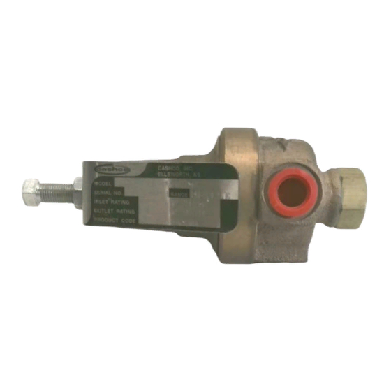
cashco 3381 Manuale di installazione, funzionamento e manutenzione - Pagina 3
Sfoglia online o scarica il pdf Manuale di installazione, funzionamento e manutenzione per Controllore cashco 3381. cashco 3381 8. Pressure reducing regulators
Anche per cashco 3381: Manuale di installazione, funzionamento e manutenzione (10 pagine)

V. SHUTDOWN
1. On systems with a bypass valve, and where sys-
tem pressure is to be maintained as the regulator
is shut down, slowly open the bypass valve while
closing the inlet (upstream) block valve. Fully
close the inlet (upstream) block valve. (When on
bypass, the system pressure must be constantly
observed and manually regulated. Close the
outlet (downstream) block valve.
VI. MAINTENANCE
SYSTEM UNDER PRESSURE. Prior to performing any
maintenance, isolate the regulator from the system and
relieve all pressure. Failure to do so could result in per-
sonal injury.
A. General:
1. Maintenance procedures hereinafter are
based upon removal of the regulator unit
from the pipeline where installed.
2. Owner should refer to owner's procedures for
removal, handling, cleaning and disposal of
non reuseable parts, i.e. gaskets, etc.
3. Refer to Figure 1, Model 3381 or 4381 for the
basic regulator and Figure 2, Model 3381 or
4381 for the cryogenic regulator. Blow-ups of
options and the composition seat trim are on
either drawing.
B. Diaphragm Replacement - Model 3381:
To prevent damage to body, use soft jaws when placng
body in a vise. Position so that vise closes over inlet and
outlet of the body.
Option-1+6 contains single diaphragm construction. In
the event of diaphragm failure, the process fluid will mix
with the loading fluid. Please alert your representative so
an alternative product can be selected.
SPRING UNDER COMPRESSION. Prior to removing the
spring chamber, relieve spring compression by backing
out the adjusting screw. Failure to so so may result in
flying parts that could cause personal injury.
IOM-3381/4381
WARNING
CAUTION
CAUTION
WARNING
SECTION V
Do not walk away and leave a bypassed regulator unat-
tended.
2. If the regulator and system are to both be shut
down, slowly close the inlet (upstream) block
valve. Close the outlet (downstream) valve only
if regulator removal is required.
SECTION VI
1. Securely install the body (1) in a vise with the
spring chamber (2) directed upwards.
2. Relax range spring (17) by turning adjusting
screw (8) CCW until removed from spring
chamber (2).
3. Loosen spring chamber (2) by placing wrench
on "flats" and rotating CCW making sure not
to use the flat where the vent hole is locat-
ed.
4. Remove spring chamber (2), range spring
(17), spring button (5) and diaphragm gasket
(14), (if metal diaphragms are used, there will
be one diaphragm gasket (14) on top and
one below the diaphragm(s). If a composi-
tion diaphragm is used there will only be one
diaphragm gasket (14) above the diaphragm
(13).
5. Remove the diaphragm subassembly con-
sisting of the pressure plate nut (10), lock
washer (9), pressure plate (3), diaphragm
(13), pusher plate gasket (15) and pusher
plate (4). NOTE: Refer to the quantity of
diaphragms (13) incorporated per the bill of
materials listing. Depending on outlet pres-
sure level, multiple metal diaph ragms may be
"stacked".
6. Loosen pusher plate nut (10) and separate
all parts (3, 4, 9, 13 & 15) of the diaphragm
subassembly.
7. Inspect pressure plate (3) to ensure no
deformation due to over-pressurization. If
deformed, replace.
CAUTION
Diaphragm Subassembly
3
