cashco CA1 Manuale di installazione, funzionamento e manutenzione - Pagina 4
Sfoglia online o scarica il pdf Manuale di installazione, funzionamento e manutenzione per Apparecchiature industriali cashco CA1. cashco CA1 12. Back pressure / relief regulators
Anche per cashco CA1: Manuale di installazione, funzionamento e manutenzione (10 pagine)
9. Remove the ITA by pull ing up on the piston-
guide bearing (13). Set ITA aside.
10. Remove the lower return spring (22) from
within the body (23).
11. Remove the cage o-ring seal (15).
12. Remove metal C-ring seal (28) from body (23)
di a phragm flange groove.
13. Clean all metal parts to be reused according to
owner's procedures. NOTE: Regulators are
originally supplied with a level of clean li ness
equal to Cashco cleaning standard #S-1662.
Contact factory for details.
C. Disassembly of the ITA:
1. To Disassemble the ITA (See Figure 2):
a. Hold the lower part of the valve plug (20)
in a bench vise; grasp in "smooth jaws"
directly under plug's (20) seating disc por-
tion on hub "flats" provided. Do not hold
on the ma chined sur face in the plug's (20)
spin dle area.
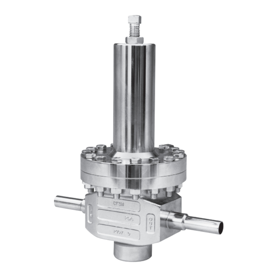
Figure 2: Assembled ITA, with
"UC" Dynamic Side Seal
b. Using a special double-posted spanner
wrench fitting (to order see NOTE in
Section IX, Parts Ordering Information),
turn the pis ton-guide bear ing (13) CCW
to loosen. The piston-guide bear ing (13)
may be re moved by hand after loos en ing.
c. Remove ITA from vise. Pull the valve plug
(20) down and out through the cage's (19)
bottom opening.
d. Examine the com po nents (27.1, 27.2,
27.3) of the dy nam ic side seal (27)
mech a nism to de ter mine if sig nif i cant
leakage was oc cur ring. If the dy nam ic
side seal shows signs of sig nif i cant leak-
age, de ter mine if op er at ing con di tions
are ex ceed ing pres sure, pres sure drop,
or tem per a ture lim its.
4
D. Inspection of Parts:
16
E. Reassembly of the ITA:
e. Remove dynamic side seal (27) com po-
nents and discard. Special care should be
taken when using "tools" to remove the
components to ensure that no scratches
are made to any portion of the piston- guide
bearing (13) groove.
f.
Remove the shim (16) from within the
cage (19).
g. Remove seat ring (21); examine for signs
of leakage. If seat ring (21) shows signs of
significant leakage, determine if op er at ing
con di tions - pres sure, pressure drop, or
temperature ex ceed design lim its.
2. Clean all metal parts to be reused according
to owner's procedures. NOTE: Regulators are
originally supplied with a level of clean li ness
equal to Cashco cleaning standard #S-1662.
Contact factory for details.
1. Remove and dis card the fol low ing parts:
o-ring (15), diaphragm(s) (9), seals (27, 28),
and seat ring (21). These parts MUST be
re placed with fac to ry supplied new parts.
2. Inspect the metal parts that will be reused. The
parts should be free of surface con tam i nants,
burrs, oxides, and scale. Rework and clean
the parts as necessary. Surface con di tions
that affect the regulator performance are stated
below; re place parts that can not be re worked
or cleaned.
3. QC Requirements:
a. Valve plug (20);
1. 16 rms finish on its seating surface
for tight shutoff.
2. No major defects on bottom guide
spin dle.
b. Cage (19);
1. 16 rms finish on cylinder bore. No
"ledg es" formed due to wear from
moving dynamic side seal (27) or plug
(20).
1. Installation of dynamic side seal (27) (See
Figure 1):
a. Type CP:
1. Stretch o-ring energizer/seal (27.2)
over low er cir cum fer ence of piston-
guide bear ing (13), tak ing care not
to "cut" o-ring energizer/seal. Us ing
thumbs, work the o-ring en er giz er/
IOM-CA1/SA1