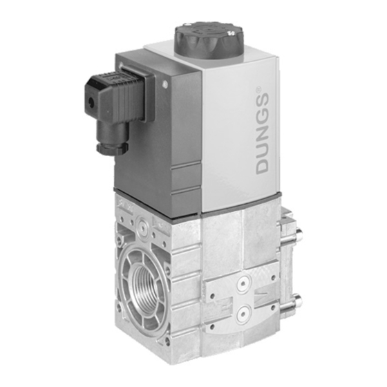
Dungs SV 1010/604 Manuale di istruzioni per l'installazione - Pagina 3
Sfoglia online o scarica il pdf Manuale di istruzioni per l'installazione per Unità di controllo Dungs SV 1010/604. Dungs SV 1010/604 6. Safety shutoff valve

Wiring the SV-(DLE)
• Disconnect all power to the valves before wiring to
prevent electrical shock and equipment damage.
• Do not exceed the electrical ratings given in the
specifications and on the valve.
• Attach flexible 1/2" NPT conduit to the DIN connector.
• Route the wires through the conduit and the DIN
connnector.
Max. Flow Adjustment (SV-DLE only)
• The SV-DLE is factory set with the max. flow adjustment
fully open.
Before making a max. flow adjustment, the valve
should be properly piped in the application.
• Locate the max. flow adjustment on top of the SV-DLE
(base of the hydraulic brake). There are two screws, the
holding screw is recessed and has a blue sealing
compound on it, while the pan head screw protrudes from
the cap.
• Loosen the pan head screw until you can freely rotate
the flow adjustment.
• Turn clockwise for less gas or counterclockwise for more
gas.
• Check the flow at the burner with an orifice or flow meter.
• Tighten the pan head screw on the adjustment cap after
adjustments are completed.
Initial Lift Adjustment (SV-DLE only)
The initial lift adjustment varies the initial gas flow through
the valve as the valve seat begins to open. This adjustment
can allow the initial gas flow to 0 % and 70% of the total
gas flow; 0 to 25% of stroke, within 1 second. All SV-DLE
valves are factory set with no initial lift (100% slow opening).
To adjust the lift proceed as follows:
• Unscrew the small black cap on top of the flow
adjustment cap to expose the initial lift adjustment knob.
• The black cap also serves as tool; turn the cap over and
insert it on the slot on the adjustment knob.
• Turn the knob clockwise for a min. initial lift or
counterclockwise for a max. initial lift.
• Once the desired initial fast lift has been achieved,
reinstall the black cap.
3 ... 6
WIRING
• Use 14 or 16 guage wire rated for at least 75˚C (167˚F).
• Connect the wiring to the appropriate screw terminals in
the DIN connector.
• Plug the DIN connector onto the terminals. Fasten
the DIN connector with the screw supplied.
VALVE ADJUSTMENT
Max. Flow Setting
Initial Lift Adjustment
CAUTION: All wiring must comply with local
electrical codes, ordinances and regulations.
Do not adjust or remove any screws or bolts which
are sealed with a Red colored compound. Doing so
will void all approvals and warranties.
