FreeAir Horten IX Manuale
Sfoglia online o scarica il pdf Manuale per Giocattolo FreeAir Horten IX. FreeAir Horten IX 4.
Anche per FreeAir Horten IX: Manuale di avvio rapido (4 pagine)

Dear customer, congratulations on the purchase of the Horten IX model. To enjoy building and flying the model most, please read
carefully the building instructions before you begin and make sure that you understand the building process. Eventually get in touch
with the manufacturer or your dealer.
Part name
Wing half of EPP
Fuselage of EPP
Instructions
Engine nacelle of EPP
Rear fuselage of EPP
You will need the following tools and materials:
Cyanoacrylate glue, cyanoacrylate glue accelerator, a sharp (modelling) knife. To complete the model you need the following: a
receiver (MZK), servos (Waypoint W-060), a DC controller (TMM or Jeti 06), a battery pack (2 LiPol cells of 600 -1000 mAh).
Description of the model:
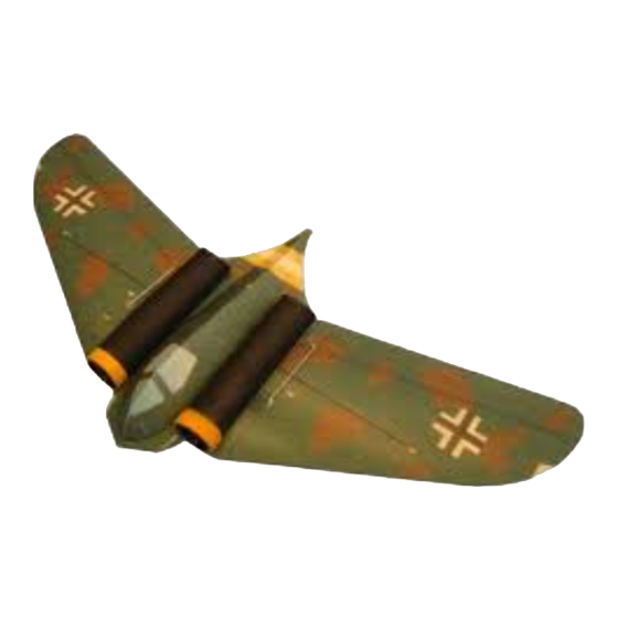
The model of the Horten Ho 229 is completely made of the EPP and is designed for pleasure flying. Its prototype was one of the
world's first turbojet powered flying wing fighters. It was developed in the closing period of the Second World War in Germany.
The model's weight beginning at 180 grams makes it an ideal type for flying at any place (such as a school playground or yard or in
the street). It is designed not only for the experienced pilots, but also for the advanced modellers. Its special silhouette gives its
flight display a very unusual and interesting atmosphere. Thanks to its well-conceived design the building time should take
something around 120 minutes. It is propelled by two GWS fans (not supplied with the kit, but can be ordered together with the
model kit). These fans provide the model with a sufficient performance without necessitating use of AC motors. The flight duration
reaches around 8 to 10 minutes.
Building the model:
All joints should be glued using the thin cyanoacrylate glue (CyA). Begin by gluing together the two wing halves (fig. 1). Using the
figs. 2 and 4 as a guide, cut a groove some 1-2 mm deep for the wing spar rod of carbon composite. Push (insert) the wing spar into
the groove, using the figs. 3 and 5 as a guide, gluing it in place with a thin cyanoacrylate. Then glue the rear fuselage part (fig. 6) in
place. Cut the cockpit enclosure with a sharp knife under an 80-degree angle so that a peaked nose would be created (fig. 7).
According to the figs. 8 and 9 glue together the cockpit enclosure. Glue the aileron horn some 12-18 mm from the aileron inner
edge (fig. 10). Using either cyanoacrylate or a five-minute epoxy, attach the fans (fig. 11). Some 40 mm behind the fans, cut the
opening for the aileron servos (figs. 12, 13), cut a 1 to 2 mm thick slice from the block of the foam removed from the servo hole (it
will come handy later on to cover the aileron servos) fig. 14. Push the servo into the prepared opening, and secure by applying the
cyanoacrylate glue to the flanges of servos (fig. 15), and cut a groove in the wing and push the servo cable into it. Then glue back a
part of the EPP originally removed there (fig. 16). Install the aileron control rods, ensuring their equal length (fig. 17). Glue the fan
cowlings in place (fig. 18). Then glue in place the EPP bottom keel, facilitating the launch of the model (fig.19). Attach the DC rpm
controller and the receiver (fig. 20); glue both devices with the cyanoacrylate glue or with a double-sided Velcro tape. Now cut the
contact edge of the cockpit enclosure wall so that it would have a bevelled edge to fit snugly against the wing (figs. 21 and 22). The
centre of gravity position is 130 mm from the nose of the model. Pin the cockpit in place and by shifting the propulsion battery set
the correct position of the centre of gravity. Then cut an opening in the wing, 2 mm narrower than the battery (this ensures the
battery would hold well in the wing) as per fig. 23. Now glue the cockpit enclosure in place. This was the last step to finish the model
and have it ready for the test flying. Set the elevons some 3-5 mm up (measured at the wing tip trailing edge), as is usual with the
flying wings; then check the correct sense of deflection of the control surfaces again and launch the model. The flight should be
without problems. The model is not an aerobatic special but an interesting-looking model for fun flying with pleasant flight behaviour
– therefore train the rolls and loops first at a sufficient altitude and with control deflections corresponding to the purpose.
Bear in mind, too, that the model is not a toy, and therefore avoid flying in places where you may endanger health or property not
only yours, but of other people as well.
Plenty of fun and all happy landings wishes FreeAir.
Stavební návod Horten
4
All manuals and user guides at all-guides.com
Horten
Part list
Pcs
Part name
2
Launch keel of EPP
1
Aileron control rod
1
Aileron horn
Wing reinforcement carbon rod (wing spar),
2
1x660 mm
1
www.freeair.cz
Pcs
1
2
2
2
Strana č.: 1 /
