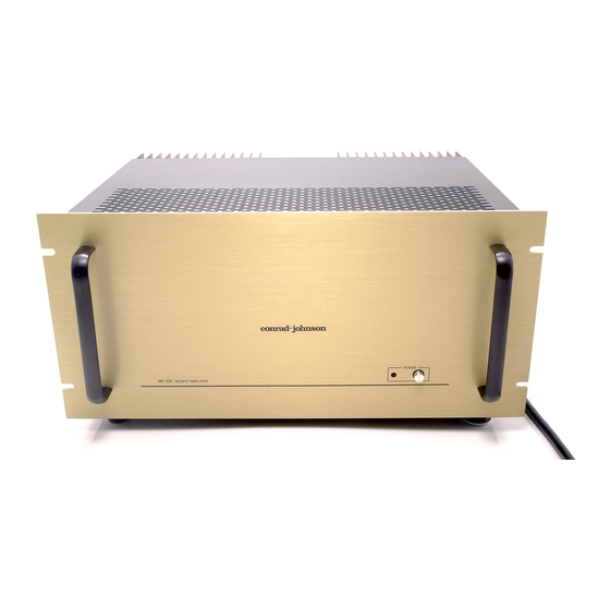
Conrad-Johnson MF200 Manuale - Pagina 4
Sfoglia online o scarica il pdf Manuale per Amplificatore Conrad-Johnson MF200. Conrad-Johnson MF200 9.

NSTALLATION
I
Because the MF200 amplifier dissipates considerable heat it is essen-
tial that proper attention be paid to ventilation. The unit should be
mounted horizontally on a flat hard surface so that the heat sinks are
unobstructed. At least four inches of clearance should be provided
above the unit, and at least two inches on the sides. The cabinet or shelf
should be open at both front and back. For more restricted installations,
cooling fans are recommended.
The front panel of the MF200 will fit in a standard 19" equipment rack
and is designed to carry the weight of the unit so that it may be rack
mounted. Again, it is important that adequate clearance be provided
above so that ventilation is not impeded. About six inches of the front of
the rack should be left open above the unit.
To minimize hum pickup, keep the unit well away from the preamplifier
and turntable and route power cords away from input cables.
THE MF200 IS TO BE OPERATED ONLY ON AC LINE VOLTAGE OF
108 TO 125 VOLTS.
The MF200 is optionally available wired for 100 volt, 120V, 220V or 240
volt, 50/60 Hz current.
CONNECTION
INPUT: Connect the preamplifier to your MF200 amplifier at the RCA
type connections located on the amplifier heat sinks.
OUTPUT: Five way binding posts are provided for connection of your
loudspeakers, with correct spacing to accept a standard "double ba-
nana" plug. They will also accept spade lugs, bare wire, or pin connec-
tors.
The two channels should be connected in correct "relative phase".This
means that when the same signal is applied to both channels, the right
and left channels speaker diaphragms should move synchronously - in
and out together. Terminals on the speakers are usually coded - one
MF200 Owner's Manual
4
