Dantel 49018 Manuale di installazione e funzionamento - Pagina 12
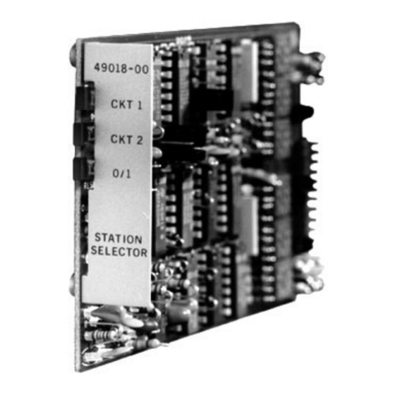
Sfoglia online o scarica il pdf Manuale di installazione e funzionamento per Apparecchiature di registrazione Dantel 49018. Dantel 49018 14. Station selector
TECHNICAL SPECIFICATIONS
DESCRIPTION
Input Voltage Range
Input Power Requirements
Idle
Full Load
Heat Dissipation
Idle
Full Load
Inputs: BCD, Power-up Clear, Reset,
Power-up Busy
Outputs: Station 1, Station 2, Clear,
Digit 1 or 0, Busy
Ring Generator Start
Station Outputs
Valid Codes
Clear Output
Reset Modes
Interdigit Time Out
Reset
Physical Dimensions
Weight
Operating Temperature Range
P
12
AGE
-10 + VDC (from host module)
CMOS, 100K ohms to -10 VDC, Logic 1 = 0 + 0.5VDC (ground),
Logic 0 = 10 + 0.5VDC, Decoded state is Logic 1
Open Drain 200 mA, -21 to -56VDC, Logic 1 = 0 + 0.5VDC
(ground), Logic 0 = 10 + 0.5VDC, Decoded state is Logic 1
Open Collector 50 mA, -56VDC max.,
Logic 1 = 0VDC (ground), Decoded state is Logic 1
2 (CKT 1 and CKT 2), strappable for 1, 2, or 3 digits
BCD 1 thru 9 and 0 for CKT 1 & 2, * & # or
A & C for clear or busy
Occurs on reset input, power-up clear input or
reset as specified below
3 seconds nominal between digits
Strappable for self-clear 3 seconds after decoding, triggered
clear from external device or from *, #, or C tone.
5.0" x 2.9" x 0.9"
VALUE
0.7 mA
18.0 mA
0.03 BTU/Hr.
0.62 BTU/Hr.
2.2 Oz.
0 to 60° C
49018-0697 <90-00089>