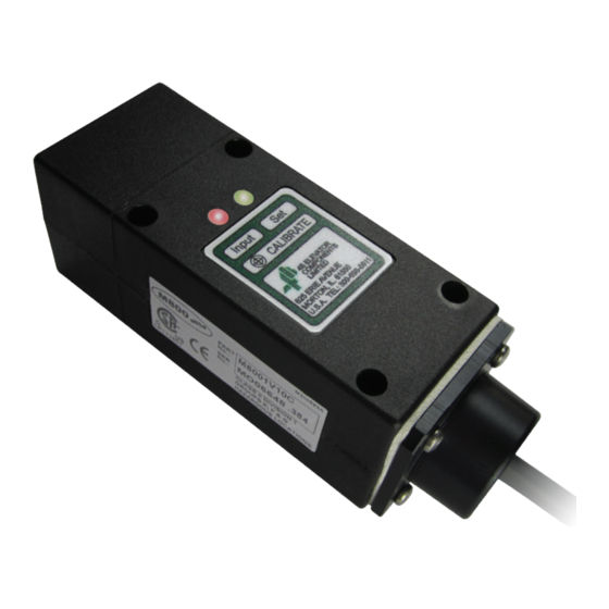
4B M8001V10C Elite Manuale operativo - Pagina 10
Sfoglia online o scarica il pdf Manuale operativo per Interruttore 4B M8001V10C Elite. 4B M8001V10C Elite 12. Speed switch

1. Check that the unit is correctly installed (see standard wiring diagram).
2. Check that the distance between the target, stud or bolt head and sensing face of M800 Elite is within
the minimum distance specified.
3. Start up machine, and wait for start-up delay to complete (set LED will be solid green).
4. 4B's SpeedMaster™ calibration and testing device can be used to accurately test the alarm and
shutdown features of the M800 Elite. A metal putty knife or a small piece of metal can be used to
simulate a stop motion situation by placing the metal between the sensing face of the M800 Elite and
the target. After the initial start up delay, the machine should shutdown.
If the system does not immediately shutdown as expected or alarm as required, then remove the
machine from service until the problem has been diagnosed and corrected.
FAULT
Set LED is Orange
Set LED is Red
Input LED does
not Illuminate
Input LED Stays
on Permanently
TESTING AND COMMISSIONING
The SpeedMaster™ with Pulse Pilot is the only device that
accurately tests the calibration of a speed switch, and allows
testing of the alarm and shutdown features of the sensor while
installed on the machine shaft.
The SpeedMaster™ operates in two modes. Input mode
is used to measure the pulse rate at normal speed. Output
mode will allow the user to input pulses to the sensor for
testing purposes.
The Pulse Pilot fits between the gap between the sensor and
Patents -
US8947073
the target. The Pulse Pilot will have no effect on the operation
MX321802
of the speed switch until it is connected to the SpeedMaster™
EP26223568
and set to "output" mode.
TROUBLESHOOTING GUIDE
Calibration not accepted, need to recalibrate sensor (see page 9).
Follow procedure "RECALIBRATION FOR A DIFFERENT SETTING". If the
set LED remains red, contact 4B.
Check that you have a supply of the correct value across the brown and blue
wires. Slide a screwdriver blade across the face of the sensor, the input LED
should flicker. If not, contact 4B.
If the input LED does flicker, move the front face of the sensor closer to the
target and check the target size as specified under "INSTALLATION".
Either increase the gap between the target and the shaft, or between the
target and the sensor face.
SPEEDMASTER™
WARNING
REMEDY
PAGE 10
