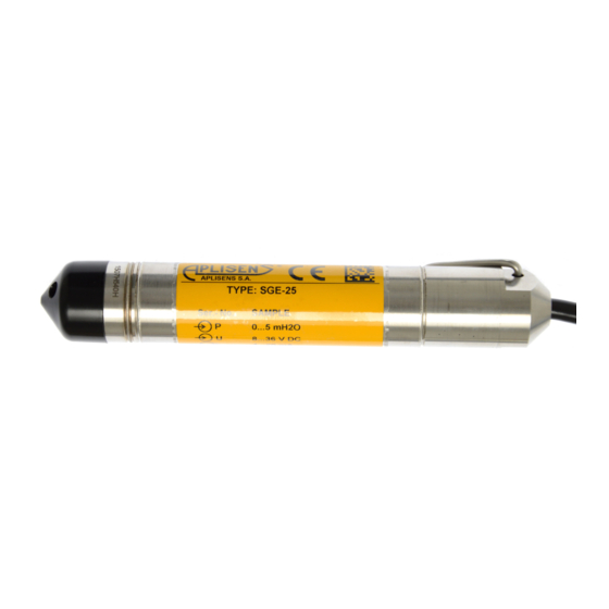
Aplisens SGE-25C Manuale d'uso - Pagina 19
Sfoglia online o scarica il pdf Manuale d'uso per Accessories Aplisens SGE-25C. Aplisens SGE-25C 20. Hydrostatic level probes
Anche per Aplisens SGE-25C: Manuale d'uso (16 pagine)

C
15. APPENDIX 1. Testing of excess voltage protection elements
(Not applicable to Ex version)
Probe (not immersed)
Figure 5a. Testing the Transil diode connected between the wires.
(Not applicable to Ex version)
a) The results for an undamaged diode should be as follows:
R=600 ,
UZ=24VDC - line current
R=2 k ,
UZ=50VDC - line current raised by approx. 1.5 mA to 5.5 mA
b) Results indicating damage to the diode:
R=600 , UZ=24VDC - line current
or when resistance is measured on the probe cable – R ≈ 11
Probe
Figure 5b. Testing the Plasma surge arresters.
(Not applicable to Ex version)
The Plasma surge arresters is working correctly if:
a) The resistance between the shorted wires of the probe and the casing at a test voltage of approx. 50V
is ≥ 0.5 G .
b) When UZ is increased gradually, the sparking voltage should be approximately 90, 250 V depending on
the type of device (attention should be paid to the value of U2, which at the moment of ignition will fall to
20 V – a reading of U1 taken at this point gives the ignition voltage).
If the protective elements do not pass the above tests, the probe should be returned to the manufacturer
for repair.
+
V1
_
4mA
voltage V1 37 ÷ 41 V
40mA
voltage V1 ok. 0,5 V
+
_
V2
17
R
+
_
R
V1
DTR.SG...04
UZ power
supply
set to 50V DC
+
UZ power
supply
up to 250VDC
_
(ENG)
