Apogee Instruments TS-100 Manuale d'uso - Pagina 11
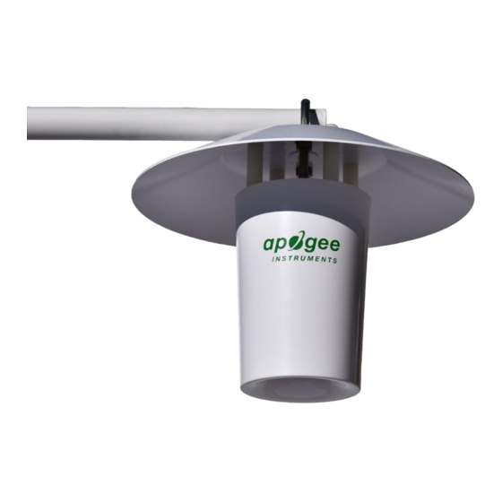
Sfoglia online o scarica il pdf Manuale d'uso per Riscaldatore Apogee Instruments TS-100. Apogee Instruments TS-100 18. Fan-aspirated radiation shield

OPERATION AND MEASUREMENT
Connect the temperature sensor or RH probe sensor to a measurement device (meter, datalogger, controller). If
you are using the ST-110, this device must be capable of inputting 2.5 V DC, and measuring and displaying or
recording a millivolt (mV) signal (an input measurement range of 0-2500 mV is required to cover the entire
temperature range of the ST-110 air temperature sensor). In order to maximize measurement resolution and
signal-to-noise ratio, the input range of the measurement device should closely match the output range of the
sensor.
Connect the fan to a 12 V DC power supply capable of supplying at least 80 mA. If the datalogger has the capability
for pulse width modulation (PWM) it can be used to reduce fan speed at night or under conditions of low solar
radiation and/or high wind speed. The datalogger or controller must have a pulse width modulation (PWM) output
of approximately 20 kHz and a duty cycle of 50 to 100 %.
The tachometer output is measured by a pulse counter. The tachometer also requires an input voltage, where
maximum voltage output to the pulse counter is the input voltage to the counter. The tachometer output allows
monitoring of the fan to ensure it is functioning properly.
The following instructions are for the ST-110 thermistor included with the TS-110 option. For wiring other sensors,
including PRT sensors, please see their respective manuals.
VERY IMPORTANT:
Apogee changed all wiring colors of our bare-lead sensors in March 2018. To ensure
proper connection to your data device, please note your serial number or if your sensor has a stainless-steel
connector 30 cm from the sensor head then use the appropriate wiring configuration below.
Wiring for ST-110 Serial Numbers 2725 and above
White: Single-ended channel (positive thermistor
lead)
Red: Excitation channel (excitation for thermistor)
Black: Ground (negative thermistor lead)
Clear: Shield/Ground
