Datakom DKG-116 Manuale d'uso - Pagina 3
Sfoglia online o scarica il pdf Manuale d'uso per Avviamento a distanza Datakom DKG-116. Datakom DKG-116 4. Manual and remote start unit
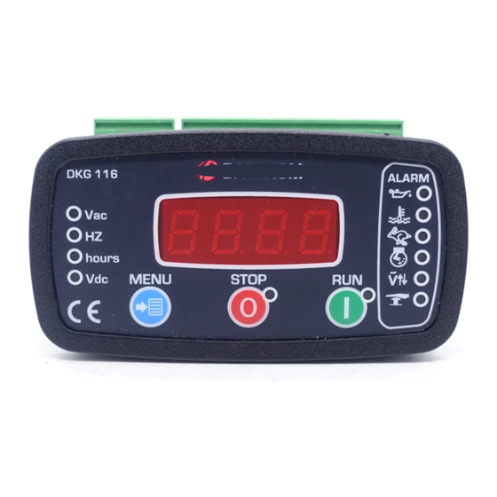
DKG-116 User Manual
Both 'High Temperature' and 'Emergency Stop' inputs must be connected
to 'Battery negative' prior to enter the programming mode.
The unit offers 12 programmable parameters listed below.
NO SYMBOL RANGE
1
2
3
4
5
6
7
8
9
10
11
12
13
14
The program mode is entered by long-pressing the MENU button. Each depression of the MENU
button will switch to the next parameter.
Another long press will enable the lamp test mode. Then any depression of MENU button will return
the display to normal mode.
If no key is pressed, then the unit will return to normal display mode with a delay.
MENU
RUN
STOP
N
MENU
RUN
STOP
N
MENU
RUN
STOP
N
PROGRAMMING
FACTORY
SET
70-500 V
170 V
70-500 V
300V
0-1000
50
0-1
0
0-1
0
0-1
0
0-3
0
0-15 sec
0
0-15 sec
10
0-7
0
0-15 sec
5
-
-
-
-
-
-
1- When genset is in off mode; press MENU button for 5 sec to
enter program mode and display the Low AC Voltage limit.
2- Press RUN or STOP buttons until requested value is displayed.
3- Press MENU button for saving the Low AC Voltage limit and
displaying the next program parameter.
4- Press RUN or STOP buttons until requested value is displayed.
5- Press MENU button for saving the parameter and displaying
the next parameter.
6- Repeat steps 4 and 5 as required.
7- Any time on settings, press MENU button for 3 sec. to exit from
program mode.
DESCRIPTION
Low AC voltage shutdown limit
High AC voltage shutdown limit
MPU crank cut frequency divided by 4
Nominal frequency: 0=50Hz 1=60Hz
Oil input: 0=pressure switch 1=level switch
Fuel output type 0:Fuel 1:Stop
Relay 3 function
0:Alarm 1:Choke 2:Stop 3:Preheat
Choke timer in seconds
Preheat timer in seconds
Connection topology:
0=1phase 1=2phases 2=3 phases 3=3 phases ,
center tapped delta (voltage checks on first 2
phases only)
4..7= same as 0..3, but voltages are not
displayed
Under/over voltage delay timer
Phase L1-N calibration value
Phase L2-N calibration value
Phase L3-N calibration value
V-03 (
30.03.2011)