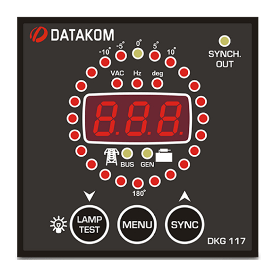
Datakom DKG-117 Manuale d'uso - Pagina 9
Sfoglia online o scarica il pdf Manuale d'uso per Pannello di controllo Datakom DKG-117. Datakom DKG-117 12. Synchroscope and check synch relay
Anche per Datakom DKG-117: Manuale d'uso (12 pagine)

DKG-117 User Manual
6. PROGRAMMING
The program mode is used to program the timers and operational limits of the unit.
To enter the program mode, press the MENU button for 5 seconds.
The program mode will not affect the operation of the unit. Thus programs may be modified
anytime, even while the genset is running.
In program mode, when the MENU key is pressed the display will show the program parameter
number, when the MENU key is released the display will show the program parameter value. The first
program number is "000".
Each depression of the MENU key will cause the display to switch to the next program parameter.
After the last parameter, the display switches back to the first parameter. The displayed parameter value
may be increased or decreased using "▲" and "▼" keys. If these keys are hold pressed, the program value
will be increased/decreased by steps of 10.
Program parameters are kept in a non-volatile memory and are not affected from power failures.
The program mode will be cancelled automatically after 20 seconds if no key is pressed.
Pgm
Definition
0
Busbar Voltage Low Limit
Busbar Voltage High
1
Limit
2
Gen. Voltage Low Limit
3
Gen. Voltage High Limit
4
Frequency difference
5
Voltage difference
6
Phase angle
7
Hysteresis Voltage
8
Pre-synchronization delay
9
Synchronization checking
at parallel
Unit
Std Val
Description
If the busbar phase voltage goes under this
V
100
limit, it means that the busbar is not energized.
If the busbar phase voltage goes over this limit,
V
500
it means that the busbar is not energized.
If the genset phase voltage goes under this
limit, it means that the genset is not running.
V
180
If the genset phase voltage goes under this limit
when the SYNCH CHECK output is energized, it
will deenergize immediately.
If the genset phase voltage goes over this limit,
it means that the genset is not running.
V
270
If the genset phase voltage goes over this limit
when the SYNCH CHECK output is energized, it
will deenergize immediately.
Hz
1.0
If the frequency difference between the busbar
and the genset is above this limit, then the
synchronization will not be accepted.
V
10
If the difference between the busbar and the
genset phase voltages are above this limit,
then the synchronization will not be accepted.
deg.
5
If the phase angle between the busbar and the
genset phase voltages are above this limit,
then the synchronization will not be accepted.
V
8
This parameter provides the busbar and genset
voltage limits with a hysteresis feature in order
to prevent faulty decisions.
For example, when the busbar is present, the
busbar voltage low limit will be used as the
programmed low limit P_000. When the busbar
fails, the low limit will be used as
P_000+P_007. It is advised to set this value to
8 volts.
sec
3
This is the time after the genset phase voltage
is within the limits (set with parameters P_002
and P_003) and the synchronization checking
is enabled.
-
0
0: further synchronization checking is disabled
when the SYNCH CHECK relay is energized.
1: synchronization checking is always
performed.
V-01
(24.03.2014)
- 9 -
