Cooke Water Witch Manuale di installazione e configurazione - Pagina 5
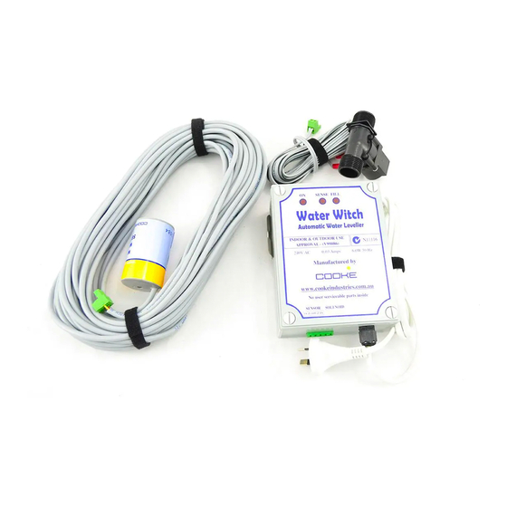
Sfoglia online o scarica il pdf Manuale di installazione e configurazione per Apparecchiature di illuminazione Cooke Water Witch. Cooke Water Witch 12. A fully automatic pool and spa water levelling system
Anche per Cooke Water Witch: Manuale di installazione (6 pagine)

Installation Guide
Control Box
Mount the control box at least 1.2 meters off the ground using the
steel bracket provided.
Solenoid
The solenoid must be installed in the water supply line using the
flow direction arrow indicated on the solenoid body.
Sensor
Refer to the diagrams 5 & 6 on the opposite page for mounting of
the sensor
The suggested method of plumbing is two 40mm class
through the pool wall and returned to the pump and filter area.
These pipes are placed approximately 300mm below normal water level and
finished off in the pool with push in eyeballs to match the other pool fittings. The
pipes are usually run along the suction and return trench and elbowed up near the
pool equipment.
These pipes must remain below the water level by a
minimum of 200mm (more is better) until elbowed into
the vertical position.
A minimum vertical height of 300mm above the top of
the pool is required for both pipes.
POOL INSTALLERS
Sensor Pipe & Fill Plumbing
Important
9PVC
pipes plumbed
3
