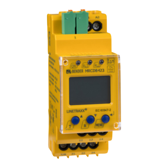
Bender LINETRAXX MRCDB423 Manuale - Pagina 6
Sfoglia online o scarica il pdf Manuale per Unità di controllo Bender LINETRAXX MRCDB423. Bender LINETRAXX MRCDB423 20. Modular residual current device type b for additional protection (protection against indirect contact) in earthed systems (tn and tt systems)

Function
2
Function
2.1
Device features
• AC/DC sensitive MRCD type B in accordance with IEC 60947-2 Annex M
• Operating characteristic type B in accordance with IEC 60755
• RMS value measurement of the residual current
• Alarm and prewarning indication via display and LEDs
• Alarm and prewarning output via relays (K1/K2)
• Measuring current transformer connection monitoring
• Fault memory
2.2
Functional description
After connecting the supply voltage U
device is in alarm state, which means that the output relays K1 and K2 are open and the installa-
tion is switched off. During start-up delay, changes on the measured residual currents do not in-
fluence the relays K1/K2. The residual current measurement is carried out via an external
CTUB101-CTBC20(P)...210(P) measuring current transformer. The currently measured value is indi-
cated on the LC display. This allows changes to be detected, e.g. when outgoing circuits are con-
nected to the system.
If the set value of the prewarning I
the output relay K1 switches and the prewarning LED lights up. The fault remains stored in the
device: The output relay K1 remains in alarm state and the prewarning LED lights until the reset
button "R" is pressed or the supply voltage is interrupted. The residual current measurement con-
tinues to be carried out.
If the set residual operating current I
elapsed, output relays K1 and K2 switch. Output relay K2 trips the circuit breaker, which discon-
nects the outgoing circuit to be monitored. The prewarning and main alarm LEDs light up. The
fault remains stored in the device: Both output relays remain in alarm state and the LEDs light un-
til the reset button "R" is pressed or the supply voltage is interrupted.
Since the installation has been switched off, residual current measurement is no longer possible.
After switching off, an automatic offset measurement is carried out. The described device combi-
nation meets the requirements of IEC 60947-2 Annex M for an MRCD protective device.
The device function can be tested using the test button "T". Parameters are assigned to the device
via the LCD and the control buttons on the front panel; this function is password-protected.
6
MRCDB423_D00396_01_M_XXEN/06.2021
, the start-up delay is active. During start-up delay "t", the
s
is exceeded, response delay t
Δn1
is exceeded, response delay t
Δn2
starts. After t
has elapsed,
on1
on1
starts. After t
on2
on2
has
