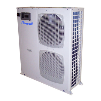
Airwell PAC HT 12-6 Manuale dei dati tecnici - Pagina 7
Sfoglia online o scarica il pdf Manuale dei dati tecnici per Pompa di calore Airwell PAC HT 12-6. Airwell PAC HT 12-6 20. High temperature air-to-water heat pumps

General Hydraulic Layout for a Type 2 (*) Installation
1
Stop valve
2
Buffer tank (optional)
3
Filter or sludge trap
4
Relief valve
5
3-way valve - Domestic hot water
6
Domestic hot water tank
7
Safety devices
8
Recycling circulating pump (optional)
9
Circulation pump
Layout 2 :
This layout is recommended for heating installations with wide operating water flow variations (radiator thermostatic valves present in the system). We strongly
recommend including the buffer tank
thermostatic valves are closed.
The flow adjustment valve
(11)
is used to balance the flow in heating mode and domestic hot water mode to always ensure optimum PAC HT operation.
HW
1
1
6
5
1
11
3
1
1
12
(2)
as it guarantees that the heating loop capacity is higher than the minimum volume when the maximum number of
1
8
3
7
CW
1
14
1
13
9
4
1
1
2
11
Flow regulating valve
12
Expansion tank
13
In-line heater
14
Bleed
15
Safety valve
HW : Hot Water
CW : Cold Water
*
Installation components not supplied
15
1
7
