Bender B94060010 Manuale di avvio rapido - Pagina 7
Sfoglia online o scarica il pdf Manuale di avvio rapido per Controllore Bender B94060010. Bender B94060010 12. Charge controller
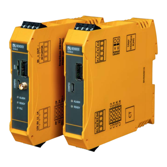
Legende
1
USB-Schnittstelle für Ethernet/WLAN/Verbindung
zum Master
2
SIM-Karten-Einschub
3
Antennenbuchse
4
Konfigurationsschnittstelle/Verbindung zum Slave
5
LEDs für:
• ALARM
• READY (Online-Konnektivität)
• PLC (Power Line Communication) - Optional
6
12 V-Spannungsversorgung
7
0 V
8
Relais 1 (Steuerspannung Schütz)
9
Relais 1 (Steuerpin Schütz)
10
Anschluss Stromwandler (optional)
11
Anschluss an Benutzeroberfläche per RJ45-Kabel
12
Anschluss Zähler
13
Steckerverriegelungsanschlüsse
i
Laderegler CC612
SIM-Karten-Einschub und Antennenbuchse
sind nur bei Datengateways mit 4G-Modem
verfügbar.
Datengateways mit 4G-Modem sind:
CC612-1M4PR, CC612-2M4PR; CC612-2M4R.
PLC ist optional.
Relais
Das Relais, das im Laderegler den Schütz steu-
ert, ist mit 30 V/1 A bemessen. Falls dieser Wert
nicht ausreichen sollte, ist gegebenenfalls ein
weiteres Relais zwischenzuschalten.
Schütz
Der Schütz der Relais kann auch an ein Kabel
mit einem Typ-1- oder Typ-2-Stecker ange-
schlossen werden.
I
V
!
orsicht
Herausziehen
Steckers!
Messstromwandler-Stecker zu
fest herausgezogen, kann das
Gehäuse mitsamt der inneren
Bauteile beschädigt werden.
Nutzen Sie eine Spitzzange zum
Entriegeln
stromwandler-Steckers.
Beschädigungsgefahr
des
Mess-stromwandler-
Wird
der
des
Mess-
CC612 Laderegler/ CC612 charge controller
Legend
1
2
3
4
5
6
7
8
9
10
11
12
13
i
Charge Controller CC612
The SIM card reader and antenna socket are
available on data gateways with 4G modem
only.
Data gateways with 4G modem are:
CC612-1M4PR CC612-2M4PR C612-2M4R
PLC is optional.
Relay
The relay used to control the contactor is rated
for 30 V/1 A. An intermediate relay may be re-
quired if this rating is inadequate.
Contactor
The relay contactor can also be connected to a
cable with a type 1 or type 2 plug.
beim
I
c
aution
CC612(4G)_D00325_06_Q_DEEN / 06.2021
USB interface for Ethernet/WLAN/connection to
Master
SIM card slot
Antenna socket
Configuration interface/connection to Slave
LEDs for:
• ALARM
• READY (Online connectivity)
• PLC (Power Line Communication) - Optional
12 V power supply
0 V
Relay 1 (Control voltage contactor)
Relay 1 (Contactor control pin)
Connection current transformer (optional)
Connection to user interface via RJ45 cable
Meter connection
Plug lock connections
! Risk of damage when pulling out the
measuring current transformer
plug! If the measuring current trans-
former plug is pulled out using too
much force, the enclosure and the
internal components may be dama-
ged. Use needle-nose pliers to un-
lock the measuring current trans-
former plug.
7