Bender B95 012 004 Manuale - Pagina 18
Sfoglia online o scarica il pdf Manuale per Controllore Bender B95 012 004. Bender B95 012 004 20. Control and indicating device for ems and eds systems

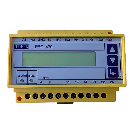
PRC470, PRC470E
Die maximale Gesamt-Messzeit (t) errechnen Sie wie folgt:
×
t
=
a
a
Anzahl der an einem EDS47x-12 angeschlossenen
Messstromwandler
24 s
Grundzeit pro Messstromwandler
n
Einstellung Anzahl der Peaks
6 s
Zeit pro Peak
Technische Daten
Isolationskoordination nach IEC 60664-1
Bemessungsspannung ........................................................................................................AC 250 V
Bemessungs-Stoßspannung/Verschmutzungsgrad ..............................................................4 kV/3
Spannungsbereiche
Versorgungsspannung U
.....................................................................................siehe Typenschild
S
Arbeitsbereich von U
.............................................................................................. 0,85 ... 1,15 x U
S
Eigenverbrauch.................................................................................................................. max. 3 VA
Messtakt
Prüfung für EDS-Systeme.................................................. wählbar: kontinuierlich/ 1 Zyklus 5 min
Prüfung für RCMS470.................................................................................................. kontinuierlich
Anzeigen
Anzeige ............................................................................................................................. LC-Display
Zeichen (Anzahl, Höhe).............................................................................................2x16 (4.5 mm)
Eingänge
Anzahl Digitaleingänge (GND - IN1 ... IN4) .....................................................................................4
Spannung max......................................................................................................................... DC 5 V
Ausgänge
Anzahl (O1+/- ... O2+/-, nur für PGH470) ....................................................................................2
Schnittstellen
Schnittstelle / Protokoll ................................................................................................. RS485/BMS
Max. Leitungslänge ........................................................................................................ ≤ 1200 m
Empfohlene Leitung (geschirmt, Schirm einseitig an PE)........................................ J(Y)STY 2 x 0,6
Abschlusswiderstand.............................................................................................. 120 Ω (0,25 W)
Schaltglieder
Schaltglieder .................................................................................................1 Relais mit 2 Wechsler
Arbeitsweise einstellbar .............................................Arbeitsstromverhalten/Ruhestromverhalten
Zulässige mechan. Schaltzahl / h........................................................................12000 Schaltspiele
Kontaktklasse...................................................................................................IIB (IEC 60255- 0-20)
Kontaktbemessungsspannung......................................................................... AC 250 V / DC 300 V
Einschaltvermögen ..................................................................................................................UC 5 A
Ausschaltvermögen............................................................................. 2 A, AC 230 V, cos phi = 0,4
.............................................................................................................0,2 A, DC 220 V, L/R = 0,04 s
Allgemeine Daten
EMV Störfestigkeit .....................................................................................................nach IEC 61326
EMV Störaussendung ...............................................................................................nach IEC 61326
Schockfestigkeit IEC60068-2-27 (Gerät in Betrieb) .......................................................15 g/11 ms
Dauerschocken IEC60068-2-29 (Transport)....................................................................40 g/6 ms
Schwingungsbeanspruchung IEC 60068-2-6 (Gerät in Betrieb).........................1 g / 10 ... 150 Hz
Schwingungsbeanspruchung IEC 60068-2-6 (Transport)...................................2 g / 10 ... 150 Hz
Umgebungstemperatur (bei Betrieb).................................................................... -10 °C ... +55 °C
Umgebungstemperatur (bei Lagerung) ................................................................ -40 °C ... +70 °C
Klimaklasse nach DIN IEC60721-3-3 ..........................................................................................3K5
Betriebsart .....................................................................................................................Dauerbetrieb
Einbaulage .............................................................................................................................beliebig
Anschlussart.............................................................................................................Reihenklemmen
Anschlussvermögen Starr / flexibel ...........................................................0,2 ... 4 / 0,2 ... 2,5 mm
Anschlussvermögen flexibel mit Aderendhülse, ohne/mit Kunststoffhülse ......... 0,25 ... 2,5 mm
Leitergrößen (AWG).................................................................................................................24-12
18
(
×
)
24s
+
n
6s
The maximum overall measuring time (t) is calculated as follows:
a
Number of measuring current transformers con-
nected to an EDS47x-12
24 s
Basic time per measuring current transformer
n
Setting for number of peaks
6 s
Time per peak
Technical Data
Insulation coordination in accordance with IEC 60664-1
Rated insulation voltage...................................................................................................... AC 250 V
Rated impulse withstand voltage/contamination level........................................................ 4 kV/3
Voltage range
Supply voltage U
....................................................................................................... see nameplate
S
Supply voltage range U
.......................................................................................... 0.85 ... 1.15 x U
s
S
Own consumption............................................................................................................. max. 3 VA
Test current
Test for EDS systems.............................................................. selectable: continuous/ 1 cycle 5 min
Test for RCMS470 .............................................................................................................continuous
Displays
Display................................................................................................................................ LC Display
Characters (number, height)..................................................................................... 2x16 (4.5 mm)
Inputs
Number of digital inputs (GND - IN1 ... IN4) ................................................................................... 4
Voltage max............................................................................................................................. DC 5 V
Outputs
Number (O1+/- ... O2+/-, only for PGH470) ................................................................................ 2
Interfaces
Interface / protocol .........................................................................................................RS485/BMS
Max. cable length .......................................................................................................... ≤ 1200 m
Recommended cable (screened, screen on one side on PE).....................................J(Y)STY 2 x 0.6
Terminating resistance............................................................................................120 Ω (0.25 W)
Switching components
Switching components ................................................................1 relay with changeover contacts
Operation adjustable ........................................................................ N/O operation / N/C operation
Permitted number of mechanical operations / h........................................ 12000 operating cycles
Contact class ....................................................................................................IIB (IEC 60255- 0-20)
Rated contact voltage........................................................................................AC 250 V / DC 300 V
Limited making capacity......................................................................................................... UC 5 A
Limited breaking capacity....................................................................2 A, AC 230 V, cos phi = 0.4
............................................................................................................0.2 A, DC 220 V, L/R = 0.04 s
General data
EMC interference immunity ......................................................................... according to IEC 61326
EMC interference emission .......................................................................... according to IEC 61326
Shock resistance IEC60068-2-27 (device in operation)................................................. 15 g/11 ms
Bumping IEC60068-2-29 (transport)............................................................................... 40 g/6 ms
Vibration resistance IEC 60068-2-6 (device in operation)...................................1 g / 10 ... 150 Hz
Vibration resistance IEC 60068-2-6 (transport)...................................................2 g / 10 ... 150 Hz
Ambient temperature (in operation)..................................................................... -10 °C ... +55 °C
Ambient temperature (in storage) ........................................................................ -40 °C ... +70 °C
Climate class according to DIN IEC60721-3-3 ............................................................................3K5
Mode of operation .......................................................................................... continuous operation
Mounting position............................................................................................................as required
Connection type........................................................................................................ screw terminals
2
Connection rigid / flexible..........................................................................0.2 ... 4 / 0.2 ... 2.5 mm
2
Connection, flexible with connector sleeve, without/with plastic sleeve ............. 0.25 ... 2.5 mm
Conductor sizes (AWG) ............................................................................................................24-12
×
(
×
)
t
=
a
24s
+
n 6s
108001 / 11.2004
s
2
2
