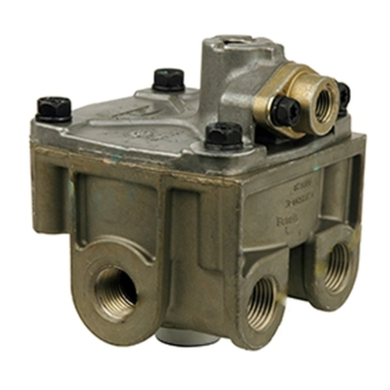
BENDIX ATR1DC ANTILOCK TRACTION RELAY Manuale - Pagina 9
Sfoglia online o scarica il pdf Manuale per Unità di controllo BENDIX ATR1DC ANTILOCK TRACTION RELAY. BENDIX ATR1DC ANTILOCK TRACTION RELAY 12. Antilock traction relay valve
Anche per BENDIX ATR1DC ANTILOCK TRACTION RELAY: Istruzioni per l'installazione (4 pagine)

8. Use only genuine Bendix
components and kits. Replacement hardware,
tubing, hose, fittings, etc. must be of equivalent
size, type and strength as original equipment and
be designed specifically for such applications and
systems.
9. Components with stripped threads or damaged
parts should be replaced rather than repaired. Do
not attempt repairs requiring machining or welding
unless specifically stated and approved by the
vehicle and component manufacturer.
10. Prior to returning the vehicle to service, make
certain all components and systems are restored
to their proper operating condition.
11. For vehicles with Antilock Traction Control (ATC),
the ATC function must be disabled (ATC indicator
lamp should be ON) prior to performing any vehicle
maintenance where one or more wheels on a drive
axle are lifted off the ground and moving.
OPERATION & LEAKAGE TESTS
GENERAL
A change in vehicle braking characteristics or a low
pressure warning may indicate a malfunction in one or the
other brake circuit, and although the vehicle air brake
system may continue to function, the vehicle should not
be operated until the necessary repairs have been made
and both braking circuits, including the pneumatic and
mechanical devices are operating normally. Always check
the vehicle brake system for proper operation after
performing brake work and before returning the vehicle to
service.
OPERATION TEST
1. Apply and release the brakes several times and check
for prompt application and release at each wheel. If a
prompt reaction is noted at some, but not all wheels,
test the antilock modulator (M-21
the ATR-1DC
™
valve and the brake chamber for proper
operation. If a sluggish response is noted at all wheels,
inspect for a kinked or obstructed air line leading to or
from the ATR-1DC
™
valve. If a complete release of the
brakes is noted at some, but not all wheels, test the
antilock modulator (M-21
™
1DC
valve and the brake chamber for proper operation.
If an incomplete release is noted at all wheels, inspect
for a kinked or obstructed air line leading to or from the
™
ATR-1DC
valve.
™
Note: The ATR-1DC
checked by applying 10 psi to the service port and noting
the pressure registered at the delivery port. Subtract
delivery port pressure from the 10 psi service pressure
to obtain the differential. Compare the measured
differential with the pressure specified for the ATR-1DC
®
replacement parts,
™
or M-22
™
) between
™
™
or M-22
) between the ATR-
valve differential pressure can be
valve part number (see the l.D. washer also for the
differential). NOTE: For ATR-1DC
incorporating a relay piston return spring (20) the
measured differential should be approximately 4 psi.
When a spring is in use, the differential will be higher.
2. Disconnect the ATR-1DC
connector from the controller wire harness. Apply the
probes of a volt-ohm meter to the connector leading to
the solenoid and note the resistance of the solenoid is
between 10 and 12 ohms. If resistance other than this
is noted, replace the ATR-1DC
3. Apply and remove vehicle power (12 vdc) to the two pin
connector half leading to the ATR-1DC
while observing the brake chambers. Note that a brake
application is made and held while power is applied to
the ATR-1DC
™
when power is removed.
LEAKAGE TESTS
1. Build the air system pressure to governor cutout. Apply
a soap solution to the exhaust port. The leakage noted
should not exceed a 1" bubble in less than 3 seconds.
2. Make and hold a full brake application and apply a soap
solution to the exhaust port and around the cover where
it joins the body. The leakage noted should not exceed
a 1" bubble in less than 3 seconds at the exhaust port.
If the ATR-1DC
™
leakage is excessive, it should be replaced with a new
or genuine Bendix remanufactured unit or repaired using
a genuine Bendix repair kit, available at any authorized
parts outlet.
VEHICLE PREPARATION
1. Park the vehicle on a level surface and block the wheels
and/or hold the vehicle by means other than the air
brakes.
2. Drain the air pressure from all vehicle reservoirs.
REMOVAL
1. Identify and mark or label all electrical wiring harnesses
and air lines and their respective connections on the
assembly to facilitate ease of installation.
2. Disconnect the air lines and wire harnesses.
3. Remove the controller and valve assembly (AT-1DC
from the vehicle. Note: The antilock controller may not
be mounted to the ATR-1DC
INSTALLATION
1. Install the assembled unit on the vehicle.
2. Reconnect all air lines and wire harnesses to the unit
using the identification made during REMOVAL step 1.
3. After installing the unit, perform the OPERATION &
™
LEAKAGE TESTS for the air valve before placing the
vehicle in service.
™
™
valve's two pin solenoid
™
valve.
™
valve (solenoid)
valve's solenoid and that it is released
valve fails to function as described, or
™
valve. Refer to Figure 1.
valves not
™
)
9
