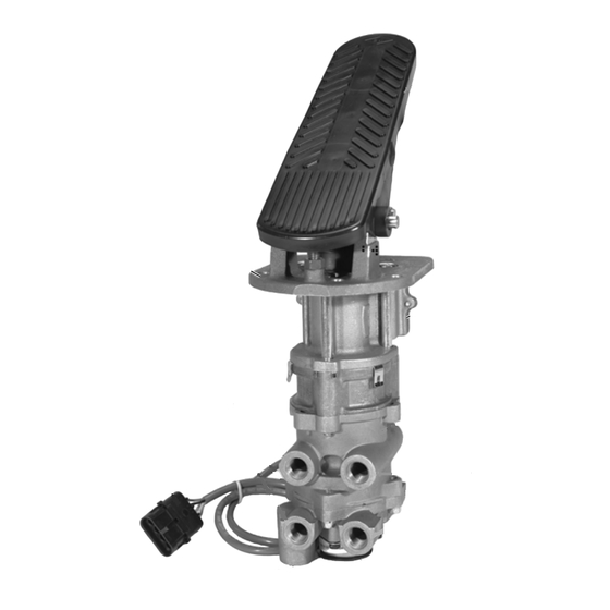
BENDIX E-10PR RETARDER CTRL BRAKEVALVE Manuale - Pagina 7
Sfoglia online o scarica il pdf Manuale per Unità di controllo BENDIX E-10PR RETARDER CTRL BRAKEVALVE. BENDIX E-10PR RETARDER CTRL BRAKEVALVE 8. Retarder control brake valve

VALVE INSTALLATION
1. Install the assembled brake valve on the vehicle.
2. Reconnect all air lines to the valve using the identification
made during VALVE REMOVAL step 1.
3. After installing the brake valve assembly, perform the
"OPERATION AND LEAKAGE CHECKS" before placing
the vehicle in service.
RETARDER BRAKE VALVE ADJUSTMENT
PROCEDURE
Equipment required to perform adjustments:
Qty.
Description
1
Air Gauge
1
Phillips Screw Driver
1
0.050 Allen Wrench
1
Volt-Ohm Meter
SWITCH ADJUSTMENTS
Adjustments to the closing of the switches can be attained
by inserting a 0.050 Allen screw, turning the screw clockwise
to decrease the amount of movement required to close the
switch and counterclockwise to increase the amount of
movement required to close the switch. All adjustments of
the switches and readings of the volt-ohm meter are to be
made with the treadle being depressed (downward stroke).
Never attempt to adjust the switches on the release of the
treadle application (upward stroke).
FIGURE 5 - RETARDER BRAKE VALVE SWITCH ADJUSTMENT
CALIBRATION OF MICRO SWITCHES ON ALL TREADLE
ACTUATED BRAKE VALVES (Except the lever actuated
model) See Figure 5.
NOTE: Cannon connector pins are identified with numbers
and Packard connector pins are identified with letters.
1. Remove the two Phillips screws and remove the cover
2. Unplug the power cable at the quick connect connector.
3. To adjust switch #1, connect the black lead of the volt-
4. To check switch #2, leave the black lead of the volt-ohm
COURSE VERTICAL
ADJUSTMENT
(SEQUENCE)
PACKARD
STYLE
CONNECTOR
CANNON
(LETTERS)
STYLE
CONNECTOR
(NUMBERED)
CANNON
STYLE
CONNECTOR
of the switch plate, exposing the switch plate.
ohm meter to pin #3 or C of the connector and the red
lead to pin #1 or A of the connector. At this time there
should be a maximum reading on the meter (open
circuit). Slowly start to depress the treadle. After
approximately 1/4" movement at the end of the treadle,
switch #1 should close and the volt-ohm meter will
respond with a reading of near 0 (closed circuit).
meter connected to pin #3 or C of the connector; connect
the red lead to pin #4 or D. At this time, the meter will
have a maximum reading (open circuit). Slowly depress
the treadle until you can feel resistance to the movement
being applied. At the point of the end of the free travel of
the treadle, approximately 1/2" movement at the end of
the treadle, switch #2 should close and the volt-ohm will
respond with a reading of near 0. If an adjustment to this
switch is required, follow the instructions under the
heading "Switch Adjustments."
SCREWS (FINE ADJUSTMENT
OF SWITCH ARM TRAVEL)
LATERAL ADJUSTER
PACKARD STYLE
CONNECTOR
7
