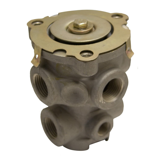
BENDIX E-2-E-3 BRAKE VALVES Manuale - Pagina 2
Sfoglia online o scarica il pdf Manuale per Unità di controllo BENDIX E-2-E-3 BRAKE VALVES. BENDIX E-2-E-3 BRAKE VALVES 4. Brake valves

When applications in the above average pressure range are
made, the valve reaches a balanced position as the air
pressure beneath the piston equals the effort exerted by the
driver's foot on the pedal or treadle. When the piston is
pressed down all the way, the inlet valve remains open and
reservoir pressure is delivered to the actuators.
Releasing
When the treadle or pedal application is released, mechanical
force is removed from the top of the piston, air pressure
beneath the piston lifts the piston; (the inlet valve is closed)
the exhaust in the valve is open and the air beneath the
piston and in the delivery lines is exhausted through the
exhaust port.
PREVENTIVE MAINTENANCE
Important: Review the warranty policy before performing
any intrusive maintenance procedures. An extended warranty
may be voided if intrusive maintenance is performed during
this period.
Because no two vehicles operate under identical conditions,
maintenance and maintenance intervals will vary. Experience
is a valuable guide in determining the best maintenance
interval for any one particular operation.
Visually check for physical damage to the brake valve such
as broken air lines and broken or missing parts.
Every 3 Months, 25,000 Miles or 900 Operating Hours
Lubricate all mechanical actuation (pedal) parts with light
(10W) oil. Apply 2 to 4 drops of oil between the plunger and
mounting plate. DO NOT OVER OIL!!!
Lever/linkage operated valves should be adjusted so that
the roller just contacts plunger. Check for integrity of mounting
plate and treadle and/or pedal.
SERVICE TESTS
Operating Test (IMPORTANT!!! Tests should be
conducted with an accurate test gauge.)
Install gauge in a delivery port or line; depress the treadle or
pedal to several positions between fully released and fully
applied positions, checking the delivery pressure on the
gauge to see that it varies proportionately with the movement
of the treadle or pedal. In the fully applied position, the
reading on the gauge should be approximately that of full
reservoir pressure. Upon release of the application, the
reading of the test gauge should fall to zero psi immediately.
Leakage Test
With 100 psi supply pressure and valve in released position,
coat exhaust port with soapsuds arid check for leakage.
NO leakage permitted.
Fully apply valve and hold application. Coat exhaust port
with soapsuds. NO leakage permitted. Coat area around
top of valve with soapsuds. NO leakage permitted.
If the valve does not function as described or leakage is
excessive, it is recommended that it be replaced with a new
or remanufactured unit, or repaired with genuine Bendix parts
available at our distributors.
REMOVING AND INSTALLING
Removing
Block and hold vehicle by means other than air brakes.
Drain air brake system.
*If only the insert is to be removed, remove retaining ring,
and pull insert out.
If entire valve is to be removed, disconnect air lines from
valve.
Remove mounting bolts and remove valve.
Installing
Clean air lines connecting to valve.
Install valve and tighten mounting bolts.
Connect air lines to valve (plug any unused ports).
Test valve as outlined under "Service Tests."
NOTE: When installing a new or rebuilt insert, precheck
movement of the inlet and exhaust valve in the
exhaust seat by depressing the insert. Precaution
should be taken to prevent damage to the inlet and
exhaust valve and the exhaust check valve grommet,
when installing the insert in the valve. After placing
the insert in the valve body, depress the exhaust
check valve seat and install the retaining ring. Make
sure the retaining ring snaps into the body groove.
DISASSEMBLY
NOTE: Disassembly and assembly instructions are keyed
to Fig. 1 sectional view.
1. Remove treadle or lever assembly, boot and plunger.
2. Depress piston assembly and remove retainer (4).
3. Remove piston assembly (7) and piston return spring (2)
from body.
4. Remove o-ring (3) from piston (7).
5. Remove cap screw (6), washer (8), spring seat (9),
and rubber spring (10) from piston assembly (7).
6. Remove retaining ring (1) and inlet/exhaust insert
assembly (11) from body.
2
