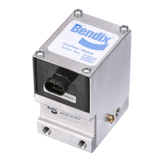
BENDIX EVERFLOW Istruzioni per l'installazione - Pagina 4
Sfoglia online o scarica il pdf Istruzioni per l'installazione per Unità di controllo BENDIX EVERFLOW. BENDIX EVERFLOW 4.

3. Make certain that adequate clearance from moving
components (e.g., drive shaft, suspension, pitman arm,
etc.) is provided.
4. Locate the Bendix
®
on the vehicle so that a minimum clearance of 1/2"
for the Bendix
AD-IP
®
AD-IS
air dryer, or 11" for the Bendix
®
dryer is above the air dryer and is available to allow
desiccant cartridge removal. An 8" minimum clearance
below the air dryer is required to allow for cartridge bolt
removal. The air dryers can be removed for servicing
the desiccant if clearance is an issue.
5. When choosing the mounting location for the assembly,
note the discharge line length requirements stated
under the heading "CONNECTING THE AIR LINES",
elsewhere in this manual.
IMPORTANT
Under normal operating conditions, the maximum inlet
air temperature for the air dryer is 160° F.
6. If possible, locate the EverFlow air dryer assembly
so that the air dryer purge exhaust does not expel
contaminants on vehicle components. If this is not
feasible, the purge exhaust may be redirected away
from the vehicle. The exhaust cover is available as a
separate item from authorized Bendix parts outlets. A
one (1) inch inside diameter (ID) hose can be clamped
on this special exhaust cover to allow the exhaust to
be redirected.
MOUNTING THE EVERFLOW ASSEMBLY
1. After positioning the assembly according to the location
requirements, mark the position of the pre-drilled
mounting holes on the selected location. Mark the hole
location using the bracket as a template. Note: Check
the vehicle manual before drilling the selected location.
2. Mount the EverFlow air dryer assembly on the vehicle
using 5/8" bolts (grade 5 min.) and washers. Torque to
25 ft-lbs (300 in-lbs).
3. Components and location used to mount the assembly
on the vehicle must be rigid enough to minimize air dryer
vibration.
CONNECTING THE AIR LINES
(Follow Figures 1, 2 & 3 for air line arrangement.)
1. For new installations, the discharge line from the
compressor to the supply reservoir can be cut and
fittings can be installed to facilitate the installation
provided that the discharge line recommendations in
the air dryer installation guidelines are adhered to.
2. Connect the compressor discharge line to the supply
port of the assembly. Connect the delivery line to the
delivery port of the assembly.
3. The Bendix EverFlow control module supply and control
line ports are 1/8" NPT.
S-1294
©2014 Bendix Commercial Vehicle Systems LLC, a member of the Knorr-Bremse Group • 06/14 • All Rights Reserved
EverFlow
air dryer assembly
®
air dryer, 2" for the Bendix
®
AD-9
®
Bendix
Tu-Flo
®
(See Figure 2.)
1. If the vehicle was previously equipped with an air dryer,
connect the control line that was disconnected to the
"GOV CON" port of the Bendix EverFlow module.
®
2. For new installations, install 1/4" tubing from the "UNL"
air
®
port of the governor to the "GOV CON" port of the
EverFlow module.
Bendix
DuraFlo 596
®
(See Figure 3.)
1. Connect the control line that was disconnected from
the air dryer control port to the Bendix
valve (delivery) to the "GOV CON" governor control port
of the EverFlow module.
Wiring
Note: The voltage of the Bendix EverFlow assembly must
be equivalent to the vehicle voltage. Since two dryers
are used in the system, fusing of the electrical line must
accommodate both heaters in the dryers and the EverFlow
module. Damage could result if not adhered to.
1. Use Bendix cable assembly kit — piece number
5008484 — to make electrical connection to dryer and
EverFlow module. Use tie wraps to secure the dryer to
the bracket.
TESTING THE AIR DRYERS
Before placing the vehicle in service, perform the following
tests.
1. Close all reservoir drain cocks.
2. Build up the system pressure to governor cut-out and
note that the air dryer purges with an audible escape
of air.
3. If the charge time exceeds 30 seconds, the EverFlow
module will activate the second air dryer. The two will
cycle in 30 second intervals.
4. Rapidly apply the service brakes several times to reduce
system air pressure to governor cut-in. Note that the
system once again builds to full pressure and is followed
by a purge at the air dryer exhaust.
5. It is recommended that the following items be tested
for leakage to ensure that the air dryer will not cycle
excessively.
(A) Total air system leakage (See Bendix publication
BW5057 "Air Brake Handbook" or visit our internet site:
www.bendix.com)
(B) Compressor unloader mechanism.
(C) Governor.
(D) Drain cock and safety valve in first (supply) reservoir.
(E) All air connections leading to and from the first
(supply) reservoir.
Compressor Installations
®
Compressor Installations
™
®
SV-1
synchro
™
4
