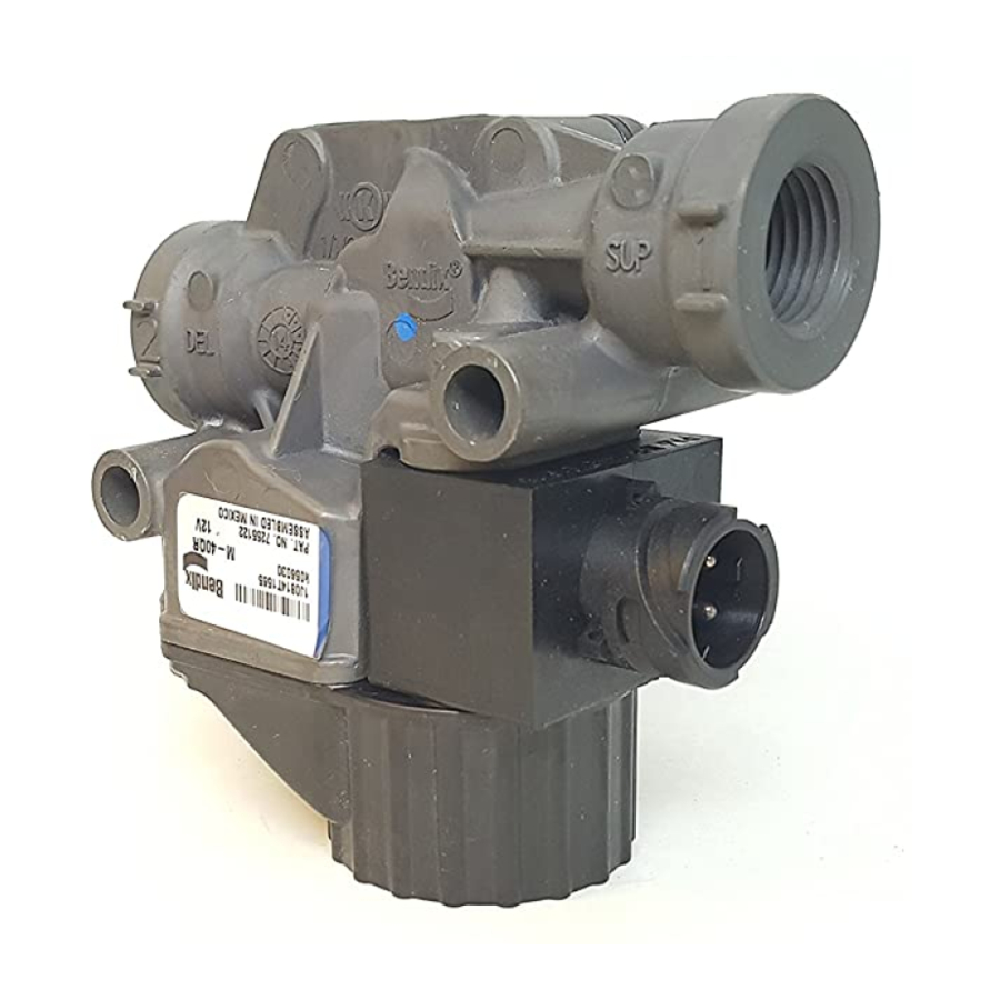
BENDIX M-40QR Dati di servizio - Pagina 5
Sfoglia online o scarica il pdf Dati di servizio per Unità di controllo BENDIX M-40QR. BENDIX M-40QR 8. Pressure modulator valves

ANTILOCK APPLY MODE
If a service brake application is made and the antilock
system detects an impending wheel lockup, the antilock
controller will make a controlled brake application using
the modulator.
In order to control the brake application, the coils of the two
solenoid valves contained in the modulator are energized,
or de-energized, in a pre-programmed sequence by the
antilock controller. When a solenoid coil is energized,
and – depending on whether the exhaust or hold solenoid
is energized – it either opens or closes, thereby causing
the exhaust or reapplication of air pressure to the brake
actuator. The solenoids in the modulator are controlled
independently by the Electronic Control Unit (ECU).
ANTILOCK EXHAUST MODE
When wheel lock is detected or imminent, the antilock
controller energizes the supply and exhaust solenoids in
the modulator.
Further delivery of air to the brake chamber is prevented,
and air is allowed to exhaust through the exhaust port.
ANTILOCK HOLD MODE
The antilock controller will place the modulator in the hold
position when information from the wheel speed sensors
shows that the correct wheel speed (braking force) has
been attained. The antilock controller will also place
the modulator in the hold position – prior to entering the
reapply mode – when it detects recovery from a locked
wheel condition.
In this mode of operation, the exhaust passage is sealed,
holding the air pressure in the brake chamber at that level.
At the same time, no application air is permitted to flow to
the brake chamber.
The modulator can enter both the antilock exhaust or
reapply mode from the antilock hold mode depending on
the needs of the antilock controller.
ANTILOCK "REAPPLY" MODE
If the antilock controller senses that wheel speed has
increased sufficiently enough to allow re-application of
braking pressure, without further wheel lock-up, it permits
the supply air to re-apply air to the brakes in the same
manner it did during a non-antilock event.
PREVENTIVE MAINTENANCE
GENERAL
Read and follow the General Safety Guidelines on
page 2 of this document.
Perform the tests and inspections presented at the
prescribed intervals. If the modulator fails to function as
described, or if the leakage is excessive, replace it with a
new Bendix
brand unit, available at any authorized parts
®
outlet.
EVERY MONTH, 10,000 MILES, OR
350 OPERATING HOURS
1. Remove any accumulated contaminates and visually
inspect the exterior for excessive corrosion and physical
damage.
2. Inspect all air hoses and wire harnesses connected to
the modulator for signs of wear or physical damage.
Replace as necessary.
3. Test air line fittings for leakage and tighten or replace
as necessary.
4. Perform the routine OPERATION & LEAKAGE TESTS
described below.
OPERATION & LEAKAGE TESTS
OPERATION TEST
This test uses the Chuff Test (described on page 3).
To properly test the function of the modulator will require
two (2) service technicians.
1. Park the vehicle on a level surface and block or chock
the wheels. Release the parking brakes and build the
air system to governor cut-out.
2. Turn the engine ignition key to the OFF position then
make and hold a full brake application.
3. With the brake application held and one (1) service
technician posted at one (1) of the modulators, turn
the vehicle ignition key to the ON position. One or
two short bursts of air pressure should be noted at the
modulator exhaust. Repeat the test for each modulator
on the vehicle. If at least a single burst of exhaust is
not noted or the exhaust of air is prolonged and not
short, sharp, and well defined, perform the Electrical
Tests.
5
