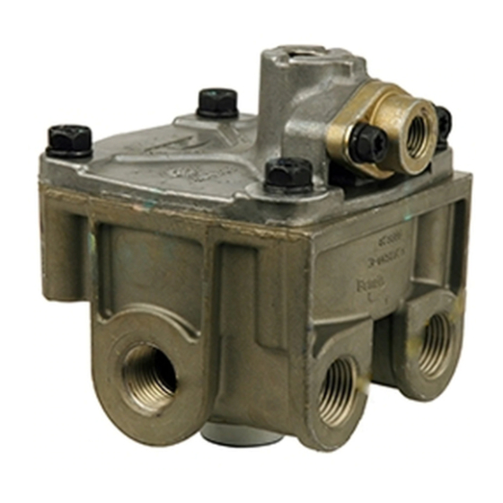
BENDIX R-12DC Manuale - Pagina 3
Sfoglia online o scarica il pdf Manuale per Unità di controllo BENDIX R-12DC. BENDIX R-12DC 8. Relay valve with biased double-check
Anche per BENDIX R-12DC: Dati di servizio (8 pagine), Istruzioni per l'installazione (4 pagine)

FIGURE 5 - R-12DC
™
BALANCE POSITION
When air pressure beneath the piston equals the service air
pressure above, the piston lifts slightly and the inlet spring
returns the inlet valve to its seat. The exhaust remains
closed as the service line pressure balances the delivery
pressure. As delivered air pressure is changed, the valve
reacts instantly to the change, holding the brake application
at that level.
EXHAUST OR RELEASE
When air pressure is released from the service port and air
pressure in the cavity above the relay piston is exhausted
through the brake valve. At the same time, air pressure
beneath the piston lifts the relay piston and the exhaust
seat moves away from the exhaust valve, opening the
exhaust passage. With the exhaust passage open, the air
pressure in the brake chambers is then permitted to exhaust
through the exhaust port, releasing the brakes.
PREVENTIVE MAINTENANCE
Important: Review the Bendix Warranty Policy before
performing any intrusive maintenance procedures. A warranty
may be voided if intrusive maintenance is performed during
the warranty period.
No two vehicles operate under identical conditions, as a
result, maintenance intervals may vary. Experience is a
BRAKE PEDAL
POSITION
HELD
BRAKE
CHAMBERS
MAINTAIN
APPLICATION
FIGURE 6 - R-12DC
valuable guide in determining the best maintenance interval
for air brake system components. At a minimum, the valve
should be inspected every 6 months or 1500 operating hours,
whichever comes first, for proper operation. Should the valve
not meet the elements of the operational tests noted in this
document, further investigation and service of the valve may
be required.
REMOVAL AND INSTALLATION
REMOVAL
1. Block and hold vehicle by means other than air brakes.
2. Drain air brake system reservoirs.
3. If entire valve is to be removed, identify air lines to facilitate
installation. Prior to disassembly, remove as much
contamination as possible from the exterior of the device
taking care to keep all contamination from entering the
open ports.
4. Disconnect air lines from valve* .
5. Remove valve from reservoir or if remotely mounted,
remove mounting bolts and then valve.
*It is generally not necessary to remove entire valve to service
the inlet/exhaust valve. The inlet/exhaust valve insert can be
removed by removing the snap ring, exhaust cover assembly
and then inlet/exhaust valve.
AIR PRESSURE
FROM BRAKE
CHAMBERS IS
EXHAUSTED
HERE
™
EXHAUST POSITION
BRAKE
PEDAL
RELEASED
AIR PRESSURE
ABOVE RELAY
VALVE IS
EXHAUSTED
HERE
BRAKE
CHAMBERS
RELEASED
3
