dymax ACCU-CAL 50-LED Manuale d'uso - Pagina 8
Sfoglia online o scarica il pdf Manuale d'uso per Strumenti di misura dymax ACCU-CAL 50-LED. dymax ACCU-CAL 50-LED 16. Led radiometer

Testing Spot Lamp Systems
1.
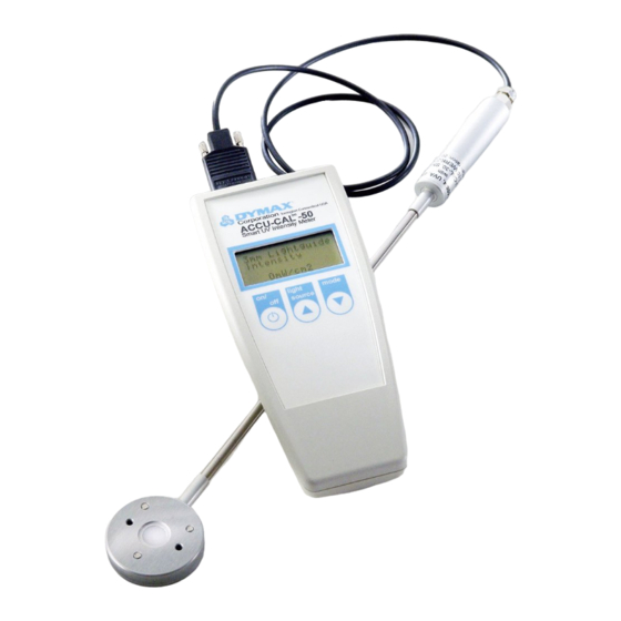
Attach the detector to the radiometer (Figure 6).
2.
Select the lightguide adapter that matches the size of the
spot lamp's lightguide. 3, 5, and 8-mm lightguide adapters
are supplied with the radiometer.
3.
Install the lightguide adapter on the end of the detector
using the two 2-mm adapter screws provided (Figure 7).
4.
Insert the lightguide into the lightguide adapter until it
bottoms out. Tighten the set screw when the lightguide is
installed.
Note: Do not over-tighten the set screw, as damage to the
lightguide may occur.
7.
Press and release the On/Off button on the radiometer's
face plate to turn the unit on.
8.
On the radiometer's display, the top line displays the light
source and the second line displays the mode.
9.
Press and release the Light Source button to select the
light source being measured. For spot lamps, use the
lightguide setting. Repeatedly press the Light Source
button until the correct lightguide size appears on the top
line. The options are:
•
3-mm Lightguide - For use when measuring energy
at the end of a 3-mm lightguide.
•
5-mm Lightguide - For use when measuring energy
at the end of a 5-mm lightguide.
•
8-mm Lightguide - For use when measuring energy
at the end of an 8-mm lightguide.
10. Press and release the Mode button to select the
operating mode. Repeatedly press the Mode button until
the mode you desire appears on the second line of the
display. The different operating modes are:
•
Peak Intensity - Shows the highest intensity in
mW/cm
2
seen by the detector during the
measurement and stores that value in the display.
•
Intensity - Shows the intensity in mW/cm
detector during the measurement. This is a dynamic
readout of intensity.
•
Dose - Shows the total energy dose in mJ/cm
detector during the measurement.
Note: This measurement is time dependent.
11. Turn on the spot lamp to begin testing.
8
Figure 6.
Attach Detector to Radiometer
Figure 7.
Adapter Installation
Figure 8.
Attach Lightguide Adapter to Lightguide (Step 4)
Figure 9.
Lightguide Source Screen
(3 mm Shown in Peak Intensity Mode)
at the
2
at the
2
U S E R G U I D E
A C C U - C A L ™ 5 0 - L E D R A D I O M E T E R
|
