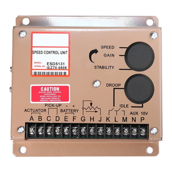
GAC ESD5131H Manuale di avvio rapido - Pagina 6
Sfoglia online o scarica il pdf Manuale di avvio rapido per Unità di controllo GAC ESD5131H. GAC ESD5131H 6. Speed control unit

peRfoRmAnCe
Isochronous Operation...................................................... ±0.25 % or better
Speed Range /Governor...........................................1K - 7.5K Hz Continuous
Speed Drift with Temperature...............................................±0.5% Typical
Idle Adjust CW..........................................Min. 1200 Hz. Below set speed
Idle Adjust CCW.......................................Min. 4100 Hz. Below set speed
Droop Range....................................................................1 - 5% Regulation*
Droop Adj. Max. (K-L Jumpered).................875 Hz., 75 Hz. per 1.0 A change
Droop Adj. Min. (K-L Jumpered)...................15 Hz., 6 Hz. per 1.0 A change
Speed Trim Range...........................................................................±200 Hz.
Remote Variable Speed Range................................................500 - 3.7 kHz.
Terminal Sensitivity
J..........................................-115 Hz., ±15 Hz/Volt @ 5 K Impedance
L.......................................-735 Hz., ±60 Hz/Volt @ 65 K Impedance
N........................................-148 Hz., ±10 Hz/Volt @ 1 M Impedance
P.........................................................10 VDC Supply @ 20 ma Max.
Dimensions......................................................................See DIAGRAM 2
Weight.....................................................................1.2 lb. (0.545 kg)
Mounting.................................................Any Position, vertical preferred
*Droop is based on a speed sensor frequency of 4000 Hz. and an actuator current change of 1 amp from no load to full load. Applications with higher
speed sensor signals will experience less percentage of droop. Applications with more actuator current change will experience higher percentages of
droop. See droop description for specific details on operation of droop ranges. When used with the ADC100 actuator the droop percentage will be less
due to the actuators low current consumption.
**Protected against reverse voltage by a series diode. A 15 amp fuse must be installed in the positive battery lead.
***Protected against short circuit to actuator (shuts off current to actuator), unit automatically turns back on when short is removed.
Application to Council Directives
Standard to which Conformity is Declared
Manufacturer's Name
Manufacturer's Address
Importer's Name
Importer's Address
Type of Equipment
Model Number
Serial Number
Year of Manufacture
I, the undersigned, hereby declare that the equipment specified above conforms to the above
Directive and Standards.
Place: Agawam, MA USA
Date:
May 6, 1999
In order to be in compliance with the above directives, the installer is obligated to install the equipment in strict accordance with the
following special instructions and guidelines.
1. The speed control unit must be mounted against the metal ground plane with four bolts, which make positive electrical
connections between the case and the back plane.
2. The magnetic pickup must be connected to the speed control using shielded cable as shown in the wiring diagram.
3. All shielded cable connections to the speed control must be connected to the case at the corner threaded connections per the wiring diagram.
4. Shielded cable for the actuator is recommended to minimize the actuator's slight movement during fast high voltage
transients. The installer's choice of not using shielded cable may cause the actuator to move more than slightly during
these transients. However, no failures should be experienced.
5. The installer must refer to the wiring diagram in the literature for proper electrical connections.
phySiCAl
ReliAbility
Declaration of Conformity
This document is subject to change without notice.
Caution: None of GAC products are flight certified controls including this item.
SpECIfICATIONS
Vibration..............................................................................1G, 20-100 Hz
Testing..................................................................100% Functionally Tested
Ambient Operating Temperature Range......-40° to +185°F (-40° to +85°C)
Relative Humidity..............................................................up to 95%
All Surface Finishes.........................Fungus proof and corrosion resistance
RoHS Regulation...........................................................................Compliant
DC Supply.........................................12 or 24 ± 20% VDC Battery Systems**
Polarity......................................................Negative Ground (case isolated)
Power Consumption......................................100 mA (No actuator current)
Speed Signal Range..................................................................0.5 – 50 VAC
Actuator Current Range @ 77°F (25°C).....................10 Amps continuous***
Agency..............................................................................CE Requirements
Heavy and Light Industrial Applications
EN55011, EN50081-2, and EN50082-2
GOVERNORS AMERICA CORP.
Agawam, MA 01001 USA
_______________________________
_______________________________
Electronic Speed Control Unit
ESD5100 Series
Above V 0000
1999 and later
Full Name:
Position:
6
enViRonmentAl
input poWeR
(Transient and Reverse Voltage Protected)
CompliAnCe / StAnDARDS
President and CEO
PIB1000 C
