GAC LSM201 Manuale - Pagina 5
Sfoglia online o scarica il pdf Manuale per Controllore GAC LSM201. GAC LSM201 11. Load sharing modules
5
INITIAL ADjUSTMENTS
This section details the adjustments and inputs available with the LSM.
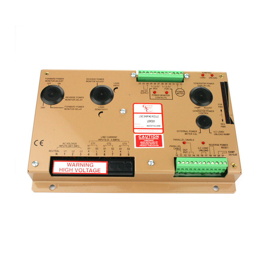
3 PHASE AC vOltAGE iNPUtS
HIGH VOLTAGE IS PRESENT AT TERMINALS N and 1-3.
The terminal strip cover must be in place when in operation
The generator's 3 phase voltages are measured at L1, L2, and L3 (Terminals 1 through 3). Terminal N must be connected to the
generator neutral. The AC voltage inputs are isolated from the battery circuits for over 5000 Volts.
The LSM200 Series has two AC voltage ranges, Low and High. Select the voltage range to match the connections
of the generator using the dip switch located in the adjustment window. The voltage ranges are wide and overlap
significantly.
•
LOW AC voltage range 100 - 280 V AV - SW1 (ON)
•
HIGH AC voltage range 240 - 500 V AC (OFF)
3-PHASE liNE CURRENt iNPUtS
Generator line currents are measured with external 5 A current transformers.
Connect the CTs with the phasing dot/start at Terminals 4, 6, and 8 as shown in the
circuits are also isolated from battery minus so that they may have one side connected to the battery minus if
required for the application.
Volt Amp burden of the LMS on CTs is very small (1.25 VA each).
DC SUPPlY vOltAGE iNPUt
Battery power, 24 V DC, must be applied to the unit at Terminals 24 (+) and 23 (-). The voltage must be in the range of 17 to 32 V DC
for proper operation.
Connections to the battery supply must come from connections at the speed control unit, or ground loops can result
in improper operation. The total current consumption is less than 160 ma. 12 V DC units are available as a special
order.
NOtE: In compliance with industry standards, all battery negatives should be commonly connected.
PARAllEl CABlE FUNCtiON AND iNtERNAl RElAY
Each individual load sharing unit communicates with other units through an analog bus signal. The parallel cable connection sends
each load sharing units signal to an external common node. Any difference in parallel cable voltage sent from one unit to the other
causes an unbalanced current to circulate in the cable. The load sharing unit senses the imbalance in the parallel cables and cancels
common mode signals. Battery minus (-) for all generators must be connected together to limit high common mode signals, indicating
an unbalanced load condition. Each load sharing unit takes action to control its governor to minimize this imbalance. The imbalance
should be less than 2 % when the system is adjusted properly.
The parallel cable voltage is proportional to the load on the generator. The voltage ranges from 0 - 7.5 V DC for a 0 - 5 A
change in CT current (real power). Measure the internal parallel cable signal, before the sensitivity adjustment, at the two
external test posts, TP1 (+) and TP2 (-) These posts are located near to the LOAD SENSITIVITY adjustment. Test post
locations are noted on the
wiring
All parallel cables must be permanently hard wired together (+ to + and - to -). When a generator is off-line, its parallel cable must be
disconnected from the rest of the units. Each LSM200 Series unit has its own internal relay to enable this disconnect and reconnection.
The parallel cable relay is closed when Terminals 13 and 14 are connected. A slave relay or con-
tacts on the generator's main circuit breaker normally operates this connection when the gener-
ators main contact is closed. The PARALLEL ENABLE LED will light when this occurs, indicating
that the internal parallel cable circuit is connected to the other units, Terminals 10 and 11.
OUtPUt SiGNAlS tO tHE GOvERNOR
Terminal 12 signals the speed controller to change generator power (speed change). It has a nominal output of 5.0 V DC with respect
to the signal ground point (Terminal 23) unless the unit is calling for a speed change. Terminal 23 must be connected to the speed
controls signal ground terminal.
Refer to the speed control's publication for the appropriate load sharing input terminal (AUX) on the speed control to which Terminal
12 (output) and Terminal 23 (signal ground) should be connected.
diagrams.
wiring
diagram. The CT
LSM200 Series Load Sharing Modules 6-2021-B1 PIB4100
5
Governors America Corp. © 2021 Copyright All Rights Reserved