GAC LSM201N Manuale - Pagina 10
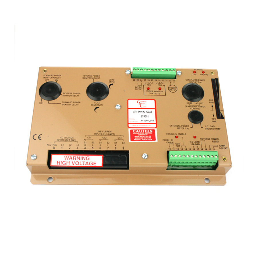
Sfoglia online o scarica il pdf Manuale per Controllore GAC LSM201N. GAC LSM201N 11. Load sharing modules
8
TROUBLEShOOTING
BEGiN tROUBlESHOOtiNG BY tEStiNG tHE FOllOWiNG
Measure the following voltages and record the readings. Perform these voltage checks under the following conditions:
•
No AC power applied to the unit
•
Terminals 13 to 14 open
•
Terminals 16 to 17 open
•
Terminals 18 to 19 closed.
tESt lOAD SHARiNG FUNCtiON
1.
Measure the battery power output. 24 V DC at terminals 24(+) and 23(-) [12 V DC for -12 versions]
2.
Measure the internal 10 V DC supply at terminals 31 (+) to 23 (-).10.6 V DC ± 0.2 V
3.
Measure the output at Terminals 12(+) and 23(-). 5.0 V DC ±0.1 V
4.
All LED's except the Load should be OFF
5.
Apply the AC Voltage to the phase voltage inputs (N, 1, 2, 3)
6.
Measure the power meters output:
Terminals 32(+) to 33(-). 0 V DC ± 0.1 V.
Terminals 33(+) to 23(-).2.0 V DC ± 0.2 V.
7.
Measure the test points TP1 (+) and TP2 (-) Parallel Cable Differential Voltage. 0 V DC ± 0.1 V
8.
Apply full power to the Generator Set (or as high as possible). In isolated mode, measure the Test Points TP1 and TP2 and note the
polarity and magnitude of the voltage. For a unity power factor condition, and a CT current level of 5 A in all phases the test points
should read between 6.0 and 7.0 V DC with TP1 being positive. If not, check the CT and Voltage phasing.
9.
With full CT current (generator set in isolated mode) applied, check the parallel cable output voltage at terminals 10(+) and 11 (-).
With a meter connected from 10 to 11 short terminals 13 and 14 to close the internal relay. Note the parallel enable LED should light.
The voltage output at terminals 10 and 11 should be adjustable via the LOAD SENSITIVITY adjustment from 0 up to the maximum as
stated in step 8. Failure to obtain the above readings, look for an open generator neutral connection, missing AC current or AC voltage
signal or SW1 voltage range switch set improperly.
10. To confirm that the Load Sharing portion is controlling the governor, temporarily connect a jumper across Terminals 10 to 11 and short
Terminals 13 to 14.
11. Apply load to the engine. The speed of the engine should fall (droop) as more load is applied to the engine. Remove engine load and
the temporary jumpers. Load sharing function is normal.
iF tHE lOAD SHARiNG iS UNStABlE FOllOW tHESE StEPS
1.
Check that the battery minus on all genera-tors are connected together.
2.
Ensure the shielded cables are connected at one end, at load sharing module as shown in the proper wiring diagram.
3.
Check to see that the case ground and the battery minus are at the same potential. See EMC/CE information in this publication.
4.
Reduce ALL load sharing sensitivity controls until the system is stable. Do not go below 25 on the sensitivity adjustment or load
sharing will be poor.
5.
If still unstable, reduce the Gain in the speed control unit slightly.
6.
Check the stability of the Automatic Voltage Regulator, including the reactive current compensation.
iF tHE ilC DOES NOt UNlOAD tO zERO POWER
1.
With ILC in unload position, measure the voltage at the test points TP1 to TP2 to determine if the LSM is sensing zero power
internally This voltage should fall to about 0.2 V DC.
2.
Condition which can prevent unloading to zero power is the AVR (Automatic Voltage Regulator) droop/cross current compensa-
tion does not track and allow the sets to have different power levels (load on the generator set is highly reactive).
3.
Improper speed setting of the governor on one or more governors.
4.
Adjust the ILC ramp time to a longer time.
LSM200 Series Load Sharing Modules 6-2021-B1 PIB4100
10
Governors America Corp. © 2021 Copyright All Rights Reserved