Gage Bilt GB568 Manuale di istruzioni originale - Pagina 8
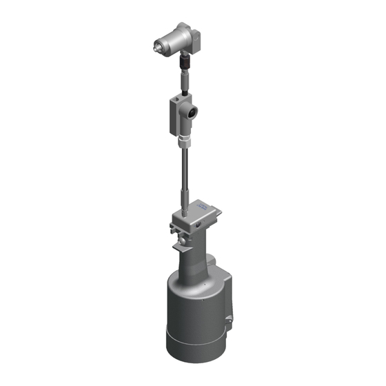
Sfoglia online o scarica il pdf Manuale di istruzioni originale per Strumenti per rivetti Gage Bilt GB568. Gage Bilt GB568 16. Installation tool
Anche per Gage Bilt GB568: Manuale di istruzioni originale (20 pagine)
WARNING:
Only qualified and trained operators shall install, adjust or use the assembly power tool for non-threaded
mechanical fasteners.
WARNING:
Operator
WARNING:
It is required that eye protection, hearing protection and safety boots be worn at all times while handling this
equipment.
WARNING:
The users or the user's employer must assess specific risks that could be present before each use based on
their application.
● Ensure there is adequate clearance for tool and operator's hands before proceeding. Keep fingers clear of any
moving parts. Keep fingers clear from fasteners and installed materials. Severe personal injury may result.
●
Verify the air lines and/or hydraulic hoses are not a trip hazard.
●
Ensure that there are no electrical cables, gas pipes, etc., which can cause a hazard if damaged by the tool
●
Verify that hydraulic hose fittings and couplings, air and electrical connections are secure before each use.
WARNING:
Do not carry from hoses or use as a hammer.
WARNING:
Do not use in explosive atmosphere.
WARNING:
Ensure air hose is securely connected to avoid possible hose whipping.
WARNING:
Always disconnect air supply, where applicable, when tool is not in use to prevent accidental start-up.
WARNING:
Do not operate when recommended pressures are exceeded as it could cause severe personal injury and or damage
the equipment.
WARNING:
Use only Gage Bilt hydraulic hoses and couplings, or equivalent, rated for 10,000 psi. (689.5 bar) working pressure.
WARNING:
Incorrect stroke will damage the nose assembly.
WARNING:
Do not dry cycle or actuate tool without fastener in place. Damage to the nose assembly could occur.
CAUTION:
Do not use beyond the design intent.
1.
Set hydraulic power unit to the recommended pressure, 6,000 psi (414.0 bar) Max. for the pull.
Gage Bilt pressure gage assembly (942280) (Sold Separately) is recommended to aid in this procedure.
"See hydraulic power unit manual for correct procedure when adjusting pressures".
Note:
Power units require a free flow of air for cooling purposes and should therefore be positioned in a
well ventilated area free from hazardous fumes.
2. Disconnect the power supply. Wipe all couplers clean before connecting. Failure to do so can result in damage to the couplers and
cause overheating. Connect hydraulic hose then the actuator.
3. Connect power supply.
4. Set stroke in accordance to nose assembly and fastener. (See checking & adjusting stroke pg. 11). (See
regarding incorrect stroke & NOT to dry cycle tool).
Note:
The tool stroke is factory set at .100" (2.54 mm). Recommended stroke point for 5/32", 3/16" and 1/4" is .100" When
adjusting the stroke, remove the nose assembly.
5. Disconnect tool from power supply.
6. Attach nose assembly. (See
6a. Remove retaining ring (401493), sleeve (568103) and
split-ring (568101). (See pg. 13 for ref.).
6b. Insert jaw and retainer assembly into stationary jaw.
6c. Slide retaining ring (401493) first and sleeve (568103) second over the rear
side of the stationary jaw. Place assembled nose assembly flush to face of
tool while inserting jaw and retainer assembly into piston of tool.
6d. Place split rings (568101) with the side containing the retaining ring
groove around rear of stationary jaw and head cylinder.
6e. Slide sleeve (568103) over split ring (568101) until it stops, attach retaining
ring (401493) into groove of (568101) split ring.
(See proper data sheet for further instructions).
7. Re-connect electric cord / air line into power supply.
Note:
The nose assembly must be perpendicular when using as it's important to the life of the nose assembly.
GB568 INSTALLATION TOOL
HOW TO SET-UP THE GB568 / GB568A
MUST
read and understand all warnings and cautions.
WARNING
above in
red
text).
6c
6b
6e
Sleeve
8
.
6,000 psi
(414.0 bar)
. for
Max
the pull
WARNING
listed above
6d
Split Ring
Retaining Ring
Sleeve
6e
Retaining Ring
Rev. 6/22