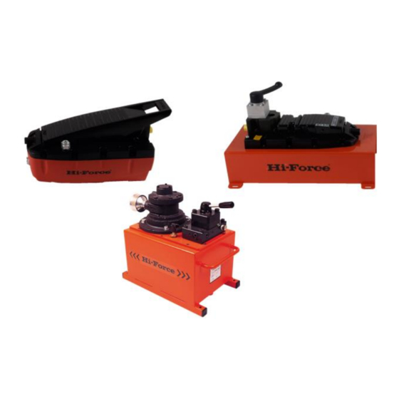
Hi-Force HAP21012 Series Manuale di istruzioni - Pagina 4
Sfoglia online o scarica il pdf Manuale di istruzioni per Pompa dell'acqua Hi-Force HAP21012 Series. Hi-Force HAP21012 Series 8. Air driven hydraulic pumps
Anche per Hi-Force HAP21012 Series: Manuale di istruzioni (8 pagine)

INSTRUCTION MANUAL – AIR DRIVEN HYDRAULIC PUMPS:
Model Series: AHP1120, AHP1120R, AHP1121, AHP1121R, AHP1122, AHP1122R, AHP1141, AHP1142,
HAP21011, HAP21012, HAP21014, HAP21016, HAP21021, HAP21022, HAP21024, HAP21026, HAP21031,
HAP21032, HAP21034, HAP21036, HAP21041, HAP21042, HAP21044, HAP21046,
If the pump is mounted vertically,
disassemble it and place it in a
horizontal position on the floor.
Place the treadle at the "PUMP" side.
There is a flat pushbutton beneath the
treadle.
Use one hand to press the "RELEASE"
side of the treadle while pressing the
pushbutton under the "PUMP" side with
your other hand (fig.10, page 13).
Maintain the pressure on the "RELEASE"
side and the "PUMP" pushbutton for
about 15 seconds.
The pump should now work correctly. If you still
have problems, repeat the above mentioned
procedure.
6.3 AHP1120R/AHP1121R/AHP1122R (Hand
Pendant Operation).
The AHP pump is extremely simple to use:
To activate the pump press the button
marked "PUMP" on the hand pendant
(Fig. 16).The pump will start to deliver
pressurized oil and thereby cause the
connected cylinder to advance.
When the button is released, the pump
stops but the pressure is maintained on
the oil side so that the connected
Hi‐Force Limited – Prospect Way – Daventry – Northants NN11 8PL – United Kingdom
Tel: +44(0) 1327 301000: Fax: +44(0) 1327 706555: Website: www.hi‐force.com
cylinder holds the load in the position it
has reached.
To return the pressure to zero and
hence retract the cylinder to its starting
position, press the button marked
"RELEASE" (Fig 16).
Fig: 16
7 - MAINTENANCE
The
routine
maintenance
below must be performed exclusively by a
skilled
technician
who
knowledge of the pump and its operation and
who
has
read
this
manual
Maintenance
must
be
maximum caution to avoid possible accidents.
This chapter describes the only maintenance
procedures
permitted.
Execution
unauthorised
maintenance
automatically invalidate the warranty and free
the manufacturer from all liability.
7.1 - Checking connections
Check
the
hydraulic
connections once a week. Ensure that the
connections on the pump are screwed down
tightly and show no signs of breakage, cracks
or other damage. Ensure that the hoses are not
damaged in any way (cuts, abrasion, cracks,
etc.).
7.2 - Cleaning the air filter
There is an air filter inside the air inlet
connection (Fig 12).
Use a slotted tip screwdriver of the
appropriate size to unscrew the filter
from the air inlet connection until it is
extracted.
Clean the filter with compressed air
and then refit and screw it into position.
Do not over-tighten the filter or
damage may ensue.
work
described
has
a
thorough
completely.
carried
out
with
of
any
work
will
and
pneumatic
