Hi-Force HAP21046 Series Manuale di istruzioni - Pagina 3
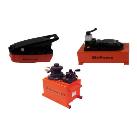
Sfoglia online o scarica il pdf Manuale di istruzioni per Pompa dell'acqua Hi-Force HAP21046 Series. Hi-Force HAP21046 Series 8. Air driven hydraulic pumps
Anche per Hi-Force HAP21046 Series: Manuale di istruzioni (8 pagine)
INSTRUCTION MANUAL – AIR DRIVEN HYDRAULIC PUMPS:
Model Series: AHP1120, AHP1120R, AHP1121, AHP1121R, AHP1122, AHP1122R, AHP1141, AHP1142,
HAP21011, HAP21012, HAP21014, HAP21016, HAP21021, HAP21022, HAP21024, HAP21026, HAP21031,
HAP21032, HAP21034, HAP21036, HAP21041, HAP21042, HAP21044, HAP21046,
with a 3/8" NPTF fitting after binding the
thread with Teflon tape.
Unscrew the breather screw (Fig: 6) by
three or four turns using an appropriate
screwdriver.
5.2.2 - Pump hydraulic connections Models
AHP1141/ AHP1142
Connect the hydraulic pressure hose to
the outlet port (Port A Fig 5) and the
reservoir port (Port B Fig 5), the hose
must be fitted with a 3/8" NPTF fitting
after binding the thread with Teflon
tape.
Use a slotted tip screwdriver to extract
the breather plug to the first click
(position D in Fig 8)
5.2.3 Pump hydraulic connections:
AHP1120R/AHP1121R/AHP1122R
Connect the hydraulic pressure hose to
(Port A Fig:14). The hose must be fitted
with a 3/8" NPTF fitting after binding the
thread with Teflon tape.
Unscrew the breather screw (Fig: 6) by
three or four turns using an appropriate
screwdriver.
5.3 Connecting the compressed air line.
Select
a
quick
compatible with the air-line supply and
connect it to the air inlet connection
(Fig. 1)
Hi-Force Limited – Prospect Way – Daventry – Northants NN11 8PL – United Kingdom
Tel: +44(0) 1327 301000: Fax: +44(0) 1327 706555: Website: www.hi-force.com
coupler
that
is
6: Operation
6.1 AHP1120/AHP1121/AHP1122.
To start the pump press down on the
treadle with your foot (Marked: PUMP
Fig. 14). This will make the pump deliver
pressurized
oil
cylinder/tool.
When the treadle pedal is released the
pump will stop delivering oil but the
pressure/load
maintained.
To return the system pressure/load to
zero, press the treadle in the area
marked "RELEASE" (Fig: 15)
6.2 AHP1141 and AHP1142.
These units are fitted with 4/3 way directional
control valves for use with double acting
cylinders.
Position 1 (Fig11/a) - oil is sent to Port 'B' and
returns to the reservoir via Port 'A' (Fig 5)
Position 2 (Fig11/b) - locked position. Ports 'A'
and 'B' are closed and the Oil flow returns to
the reservoir.
to
the
connected
in
the
system
is