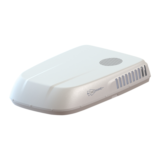
Aircommand IBIS 3 Manuale di istruzioni per l'uso - Pagina 7
Sfoglia online o scarica il pdf Manuale di istruzioni per l'uso per Condizionatore d'aria Aircommand IBIS 3. Aircommand IBIS 3 19.

Ibis 3 Owners Guide
INSTALLATION
Mark out the position of the
unit based on the following
important requirements:
Before cutting holes through the roof
ensure that mains power or battery driven
inverters are
The unit requires a 360 x 360mm square hole for
installation.
The Ibis 3 should be placed as close as possible to
the centre of the caravan or RV so that conditioned
air can circulate evenly.
Ensure that the air outlets will not be blowing
directly onto obstructions.
Consideration should be given to service access.
Ensure that location of hatches, solar panels,
antennas etc will not prevent access for service
personnel.
The roof MUST be strong enough to support the
weight of the unit (46kg + 2kg indoor unit). Contact
your caravan manufacturer to confirm that this load
can be supported by the roof.
EXTERNAL CLEARANCE. The path of the
outside fan exhaust must be free. A gap of at least
50mm is required between the roof top unit and
.Figure 1
any obstructions
Figure 1 - Foot print of the roof top air conditioner over
360 x 360mm mounting hole. The area at the back
(shown in
cross hatch) must
obstructions.
disconnected
be
kept
free
Revision V1
INTERNAL CLEARANCE The inside plenum has
a foot print of 535 x 535 mm centered around the
installation hole.
Figure 2- Inside plenum foot
The installation hole must be boxed up with
material that is strong enough to withstand the
compression from the hold down bolts. 20mm wide
timber would be required at a minimum.
Contact
Aircommand
significantly from that prescribed above.
1. Cut installation hole
WARNING
There may be electrical wiring located in
the ceiling space. Ensure that power is properly
disconnected at the supply (mains and/or battery).
Failure to do so may result in personal injury or
death.
Once the position of the unit has been determined
cut out the 360 x 360 installation hole and boxed
up.
Ensure that the main power supply for the unit has
been led through and is available for connection.
The installation hole must be sealed from the
ceiling space to prevent air conditioned air leaking
into the ceiling cavity.
of
Page 7 of 19
Figure 2
print.
if
your
installation
differs
