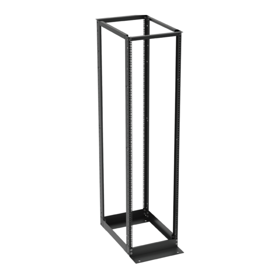
Great Lakes 4P-45U29M6 Manuale di istruzioni per l'installazione - Pagina 5
Sfoglia online o scarica il pdf Manuale di istruzioni per l'installazione per Cremagliere e cavalletti Great Lakes 4P-45U29M6. Great Lakes 4P-45U29M6 12. 4 post equipment racks

TOE OUT
MOUNTING
TOP VIEW
16.00"
20.31"
ASSEMBLY
1. Assemble top and bottom width brackets to uprights (place the
TOP VIEW
TOP VIEW
bracket with the Great Lakes label on the top). Do not tighten. Bottom
width brackets can be assembled with toe out or toe in mounting.
2. Assemble the top and bottom depth brackets to the uprights
and stand assembly up, Make sure rack is square and then
tighten all hardware. (54 ft-lb torque is recommended).
3. Secure rack to floor. All racks should be bolted to a masonry floor,
or to an equally stabilizing and secure surface, after desired location
is determined. Hardware is not provided for bolting rack to the floor,
Great Lakes' AK101 Seismic Anchor Kit is recommended for masonry
floors.
4. Locate the hole near the IEC 60417 earthing symbol on the upright
and attach the main protective earthing lug. Note: The same hardware
pack for grounding is supplied with 4PM6 and 4P1224 racks. #12-24
screw and #12 Ext. Tooth Washer will not be used when installing the
protective earthing lug on the 4PM6.
4 MOUNTING HOLES Ø.75"
TOE IN
MOUNTING
TOP VIEW
TOE IN MOUNTING
TOE IN MOUNTING
TOP VIEW
FRONT VIEW - 19"EIA MTG.
FRONT VIEW - 19"EIA MTG
16.00"
20.31"
TOP VIEW
D
C
B
5
