Hi-Force HP110 Manuale di istruzioni - Pagina 6
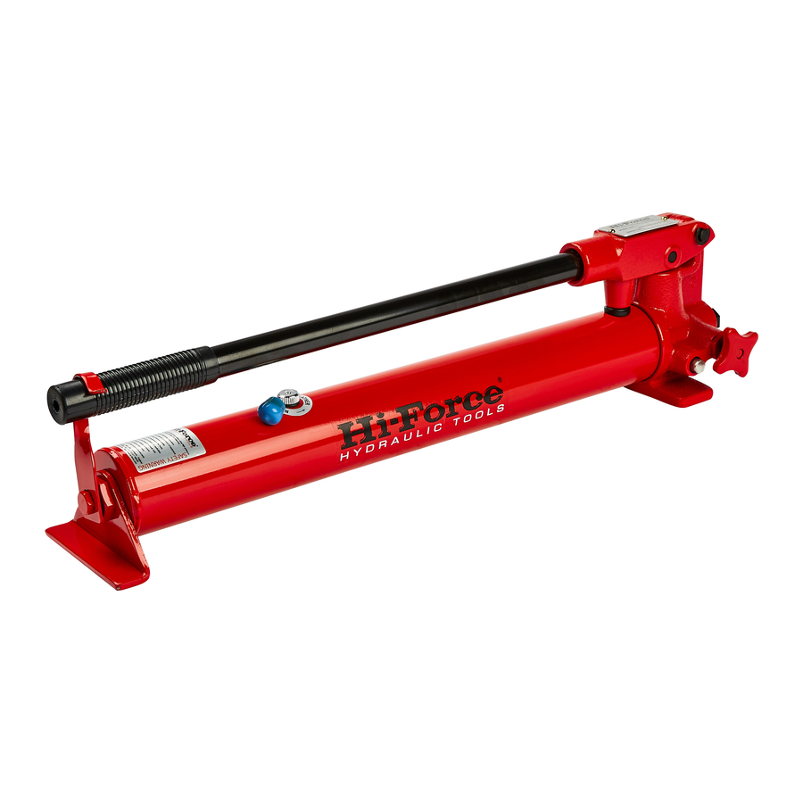
Sfoglia online o scarica il pdf Manuale di istruzioni per Martinetti Hi-Force HP110. Hi-Force HP110 6. Manually operated hydraulic pump - steel
Anche per Hi-Force HP110: Istruzioni per l'uso (4 pagine), Manuale di istruzioni per l'uso (13 pagine)
Model Series: HP110, HP227-257, HP211-252D, HPX1500-2800
Other accessories
All accessories that are connected to the
pump must be designed for a working pressure
that is at least equal to the maximum working
pressure of the pump.
Connecting cylinders/tools
Cylinders or tools can only be connected to
the pump when the system is depressurised.
Always make sure that the release knob is in
the open position (Figure. 1) before connecting
any accessory equipment.
OPERATION OF THE PUMP
Rotate the release valve clockwise (figure; 2)
until it seats, then raise the pump handle.
The low pressure piston is withdrawn. The
stationary high pressure piston mounted in the
valve body is simultaneously withdrawn from
the hollow low pressure piston. The vacuum
that is then created both in the low pressure
piston's pump bore and inside the piston
causes oil to be sucked from the oil container
via a passage, past the two intake balls and
into each other, the intake balls close and the
oil from both the high and low pressure piston is
forced past the discharge ball and out into the
discharge connection.
When the load on the pump increases to
around 20-30 bar, a valve opens a passage
between the low pressure pump piston's pump
bore and the oil container. The low pressure
function is now disengaged. Only the high
pressure piston is working.
The safety valve opens a passage between the
high pressure piston and the oil container when
the load reaches maximum working pressure.
When the release valve is turned anti-clockwise
(Figure 1), a passage is opened between the
discharge connection and the oil container
allowing the pressure to be released.
Figure: 2
Maintenance
To ensure reliable operation and long life it is
important to carry out maintenance at set
intervals. You should always follow these simple
rules:
Hi-Force Limited – Prospect Way – Daventry – Northants NN11 8PL – United Kingdom
Tel: +44(0) 1327 301000: Fax: +44(0) 1327 706555: Website: www.hi-force.com
INSTRUCTION MANUAL – HYDRAULIC HAND PUMPS:
Always make sure that:
• The pump is cleaned before returning to
storage.
• Lubricate moving parts.
• Check that there are no external hydraulic oil
leaks.
• Make sure the pump has not suffered any
external damage, as a result of impacts, etc.
Servicing
Checking the oil level
The oil level should always be measured when
the cylinder/tool is in its lowest or retracted
position.
The filler hole on the hydraulic oil reservoir is also
used to check the level. Position the pump with
the pump head facing downwards, and
remove the filler plug. The level is correct
when the oil reaches the bottom edge of the
filler hole. Refit the filler plug, tightening it to a
maximum torque of 20 Nm.
OIL LEVEL
Place the pump on a horizontal surface,
remove filler cap from the oil tank. Fill-up with
the recommended grade of oil until the level is
approx. 20mm from the bottom of the filler
hole.
BLEEDING
Place the pump on a bench or similar, with the
pump head slightly inclined downwards and
the ram on the floor standing on its pressure
head. Pump up to approx. half its stroke and
leave to stand for a few minutes. Allow the ram
to retract very slowly. Repeat this operation a
few times until all the oil has been bled from the
system. In order to bleed the pump system
separately, pump with the release valve fully
open (Figure 1).