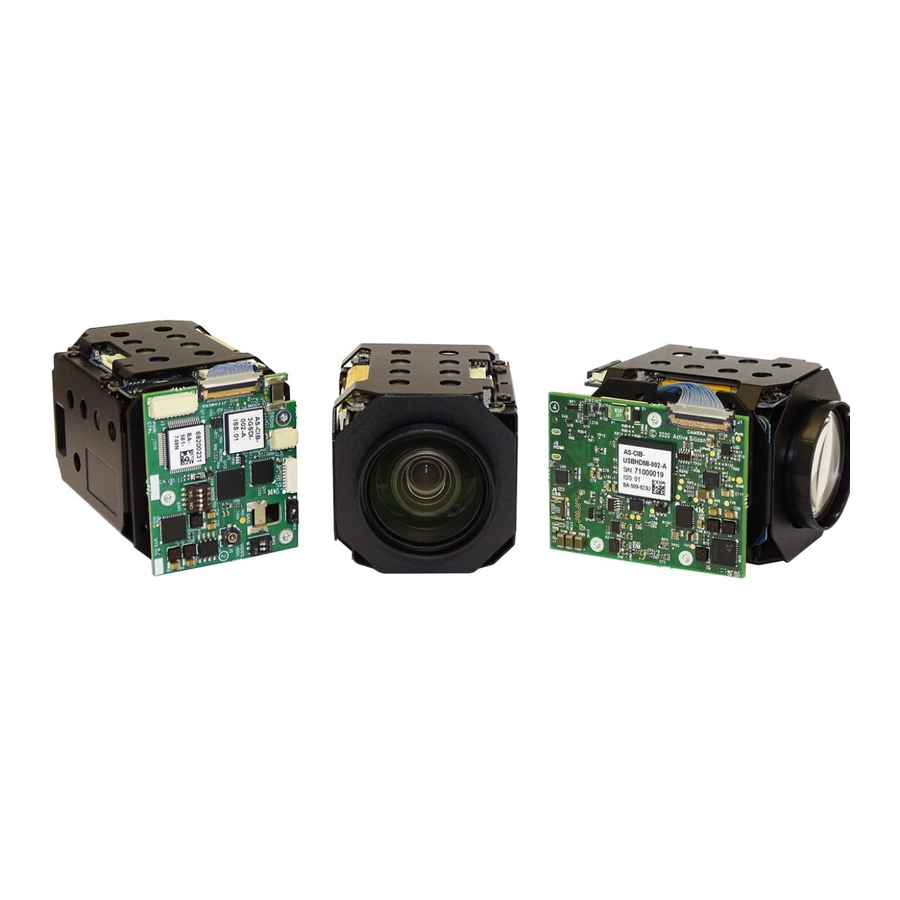
Active Silicon HARRIER Manuale di avvio rapido - Pagina 4
Sfoglia online o scarica il pdf Manuale di avvio rapido per Apparecchiature di registrazione Active Silicon HARRIER. Active Silicon HARRIER 15. Usb/hdmi camera interface board

If you have installed the Harrier USB SDK you will also be able to use the Harrier Virtual COM port to
control the camera using VISCA commands from an application that uses standard COM ports, e.g.
the
Tamron Camera Control Application
UVC Example Application - Harrier USB SDK
To evaluate the USB video capability, you will need a USB Video Class (UVC) application.
If you do not have a UVC application you can download the
website. When you install this SDK, it will create a folder with working UVC example application
called HarrierView. For information on how to use the application please see the section
Using the HarrierView UVC Application
Tamron Camera Control Application
To evaluate the serial communications capability or Harrier Virtual COM port, you will need an
application that can provide RS-232, RS-485 or TTL serial communication via a COM port.
If you do not have a serial camera control application download the
Application
for your camera model from the Active Silicon website.
For information on how to use the application please see the section
Using the Tamron Camera Control Application
Setting the Camera Control Interface (DIP Switches)
The Harrier USB/HDMI Camera Interface Board supports serial communication over RS-232, RS-485
and TTL communications interfaces (on the J3 connector). The camera can be controlled by
sending VISCA commands over the serial interface (usually via a COM port), or over the USB
connection using the Harrier Virtual COM port (if installed), or by using UVC commands.
You can select which one of these you want to use by setting DIP switches 5, 6 and 7 on the Harrier
USB/HDMI Camera Interface Board when the board power is off.
SW1-7
SW1-6
OFF
OFF
OFF
OFF
OFF
ON
OFF
ON
ON
OFF
Table 1. Harrier USB/HDMI Camera Interface Board DIP switch settings for selection of
camera communication interface before board power-up.
On the Harrier Evaluation Board, J103 supports RS-232 and TTL communications, J203 supports
RS-485 and TTL communications.
The Harrier USB/HDMI Camera Interface Board is shipped by default with all DIP switches in the
"OFF" position. In this state, the board is configured for RS-232 communications.
March 2021
HARRIER USB/HDMI CAMERA INTERFACE BOARD
(this is also available from the Active Silicon website).
below.
below.
SW1-5
COMMUNICATIONS MODE
OFF
J3: RS-232 VISCA
ON
J3: RS-485 VISCA termination enabled
OFF
J3: RS-485 VISCA termination disabled
ON
J3: TTL VISCA
OFF
J6: USB3.0 SuperSpeed (UVC/USB Virtual COM port)
QUICK START GUIDE
Version 1.7 – March 2021
Harrier USB SDK
from the Active Silicon
Tamron Camera Control
Page 4 of 14
