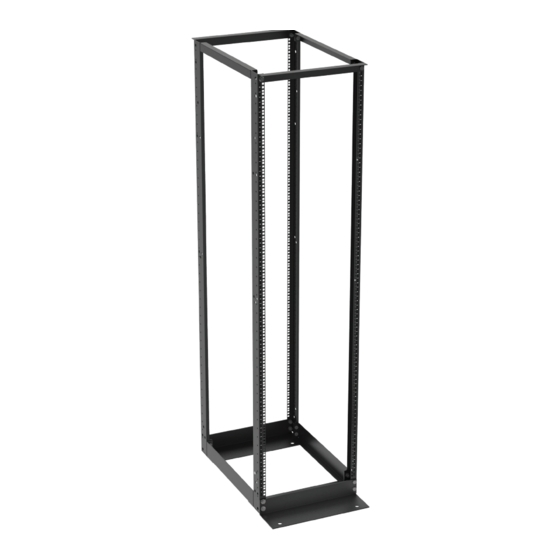
Great Lakes UL60950-1 Manuale di istruzioni per l'installazione - Pagina 6
Sfoglia online o scarica il pdf Manuale di istruzioni per l'installazione per Cremagliere e cavalletti Great Lakes UL60950-1. Great Lakes UL60950-1 8. 4 post equipment racks
Anche per Great Lakes UL60950-1: Manuale di istruzioni per l'installazione (13 pagine), Manuale di istruzioni per l'installazione (12 pagine)

OVERVIEW
2 Post Racks are designed to securely hold 19" or 23" rack mount equipment, networking equipment,
phone equipment, etc. in tight spaces or closets.
Your package includes the following items:
COMPONENT ............................................................................................................................. QTY.
VERTICAL UPRIGHT CHANNEL .................................................................................................... 2
BASE ANGLE ................................................................................................................................. 2
TOP ANGLE .................................................................................................................................. 2
½"- 13 X 1 HEX BOLT .................................................................................................................. 12
½" LOCK WASHER ....................................................................................................................... 12
#12-24 X ½"LG. SCREWS ............................................................................................................ 50
2 BARREL GROUND LUG ............................................................................................................. 1
TOOLS REQUIRED: ¾" SOCKET OR WRENCH AND A LEVEL OR CARPENTER SQUARE
ASSEMBLY INSTRUCTIONS
STEP 1
Install top angles to vertical upright channels.
A. Lay vertical upright channels on edge so
tapped holes face you and the floor. Be sure
open sides of upright channels face each other.
B. Align holes in top angle with corresponding holes in
vertical uprights. Formed leg of top angle should be
facing toward you.
C. Install 2 hex head bolts and lock washers. Finger
tighten only.
D. Turn vertical upright assembly over (rotate 180 degrees)
and repeat steps B and C. Finger tighten only.
6
