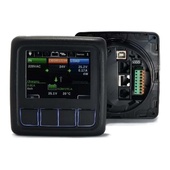
ADELSYSTEM DPY351 Manuale di istruzioni - Pagina 3
Sfoglia online o scarica il pdf Manuale di istruzioni per Monitor ADELSYSTEM DPY351. ADELSYSTEM DPY351 4. Monitor and control panel for adelbus network

Reference
Description
1
Temperature Probe (AUX1)
2
Ethernet (AUX2)
3
ADELBus: Canbus, ModBus (AUX3)
4
USB (AUX4)
5
Auxiliary Power, I/O port (AUX5)
6
Dip-switches (Hardware Config.)
3.3.1
Auxiliary temperature sensor (AUX1)
Auxiliary temperature sensor connection (RJtemp accessory
probe) to measure the temperature environment in custom
situations.
3.3.2
Ethernet Connection (AUX2)
"HUB" Collector function of the connected devices to the
ADELBus network, to transport via Ethernet. The available
protocols are the Modbus TCP / IP, the SNMP protocol and the
MQTT.
3.3.3
PowerBus Connection (AUX3)
Automated RJ45 cable connection for Modbus and Canbus
protocols. The Display must be powered via the Aux5 connector
If the power is not enough.
3.3.4
USB Connection (AUX4)
USB Connection for Software Updates via PC.
3.3.5
Auxiliary Input Power (AUX5)
Connect the positive wire to terminal 1, the negative wire to
terminal 2 of the connector.
Use a 3mm flat blade screw driver to push in the Spring
Connector.
3.3.6
Wire size (AUX5)
Use appropriate wire size to connect the AUX power supply to
the battery.
-
Wire diameter Ø 1 mm (18AWG) 2.5 mm (13AWG)
-
Fuse: Insert a 1A fuse in the positive battery line.
3.3.7
Automatic
Power
(Aux6)
The device power ON in manual Condition from Push
Button power On, otherwise can start up in Automatic
Power On. For this function set Switch 4 in position
On
3.3.8
Input/Output State Terminal 3,4,7,8 (AUX5)
The device is equipped with N°2 digital Input (terminal 3,4)
suitable to reading conditions. They can be used for the most
various checks. For example: the control of opening doors,
presence of Earth, verification of presence Light, gas, pressure,
etc...
The Output relay (terminal 7,8) could be drived in dependency
of input state by "Event" function.
- Output Relay Free Switch Contact (NO)
Max. current can be switched (EN60947.4.1):
Max. DC1: 30 Vdc 1 A; AC1: 60 Vac 1A
Min.1mA at 5 Vdc (Min Resistive load)
On
Display
3.4 Ethernet Configuration
Configuration of the Ethernet interface by HTTP server via Web
browser:
3.4.1
Connect HTTP server for the first time
The first access to the DPY351 internal webserver must be done
by means of a browser at the DPY351 factory-default IP
address, which is 192.168.1.100 using a standard CAT5e or
higher LAN cable connected to the AUX2 connector (RJ45,
shielded) on the back of the unit, as shown in Fig.1. First access
must be done at standard HTTP port, port number 80; please
make sure that this port is avaible. Type
into any browser's address bar.
At the login page, the following details must be used:
Username: admin
Password: admin
3.4.2
Customizing the ethernet interface and
services
In the setup page the following groups of parameters are
displayed:
•
Account
•
TCP/IP Configuration
•
SNMP v2c
•
MQTT
Account:
The Account group (Fig. 2) allows the customization
of the data for the HTTP server login page.
Fig. 2 – Account settings
TCP/IP Configuration
Fig. 3 shows the TCP/IP Configuration group of parameter
default values. They allow unique identification of the unit in the
network.
Fig. 3 – IP settings
If "Dynamic (DHCP)" is selected, the IP address is automatically
assigned by a DHCP server, that must be active on the network,
and the System IP, Subnet Mask and Gateway textboxes are
not available.
HTTP Port allows redirecting the HTTP traffic to a port different
than the TCP port 80, which is the one devoted to HTTP. In the
case "HTTP Port" checkbox is not selected, the HTTP protocol
will be run on port 80 and the "HTTP Port" textbox will be hidden.
If "HTTP Port" checkbox is selected, then the "HTTP Port"
textbox should be populated with the TCP port number the
HTTP traffic must be redirected to. In such a case, access to the
http://192.168.1.100
