Hi-Velocity RBM-100 Manuale di installazione - Pagina 6
Sfoglia online o scarica il pdf Manuale di installazione per Unità di controllo Hi-Velocity RBM-100. Hi-Velocity RBM-100 12. Rbm refrigerant base module
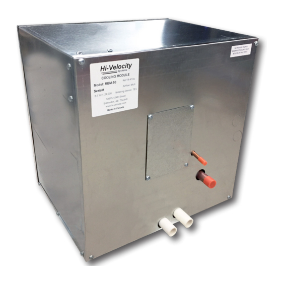
Thermal Expansion Valve & Sensing Bulb
The Thermal Expansion (TX) Valve comes pre-installed inside
the RBM Module. It is acccessible through the easy to remove
front door or access hatch. The access hatch is used to access
the TXV and the adjustment stem after the line sets are brazed
on, and can be adjusted while the system is running. The TXV's
sensing bulb is pre-installed on a clean, horizontal section of the
suction line. It will be mounted on the top half of the pipe in
the 2 o'clock or 10 o'clock position. (Fig. 13) When brazing near
components always use a wet rag or heat dissipating paste to
avoid damage or overheating any compontents. Failure to do
so may void warranty.
12 o'clock
END
VIEW
Freeze-Stat
10 o'clock
2 o'clock
Sensing
Sensing
Bulb
Bulb
Sensing
Bulb
Fig. 13 - TX Sensing Bulb
Access Ports
When refrigerant lines are connected to the RBM coil, high
and low side access ports must be connected as well. (Fig. 01 -
reference 2 & 10) With the use of a tee and reducer this process
is simplified. The access ports are required for system startup and
for future trouble shooting or service. When reading refrigerant
pressures/temperatures, always read them at the evaporator
access ports.
External Equalizer Line
The external equalizer line comes pre-installed off of the
TX Valve's body and runs to the suction line.
compensate for refrigerant pressure drop through the coil.
Freeze Stat
The RBM Series cooling module comes with an
anti-freeze control. This freeze control serves the
purpose of preventing severe icing of the coil in the
event of an undercharge or low load on the coil.
Important: Anti-freeze control must be
used at all times. Failure to do so may
void warranty.
During start-up, it is acceptable to jumper across the Freeze-
Stat. This will prevent the freeze-stat from shutting the system
off while charging a new system that may be low on refrigerant.
Once charged and running, this jumper must be removed and the
Freeze-Stat connected to the FZ and FZ terminals on the Printed
Circuit Board. Should wiring needs arise in which the outdoor unit
is controlled through another means of wiring, the Freeze-Stat
should be connected in series on the input side of the control
wiring.
www.hi-velocity.com
Freeze-Stat
It is required to
-6-
-6-
RBM Refrigerant Base Module Installation
Refrigerant Bypass
All RBM coils come with a pre-installed check valve ready TX
valve, used for AC only or heat pump condensing units. Third
party TX valves may require a bypass check valve.
Fig. 14- Bypass check valve
Drain Connections, P - Trap &
Secondary Drain Pan
Important: Piping the condensate lines on a return side cooling
coil can be dramatically different, be sure to read info below.
The primary condensate drain must have a minimum 3"
P-Trap installed (Fig. 15). The drain line must run at a slope of
¼" per foot in the direction of the drain. RBM modules come
with a ¾" male CPVC primary and secondary outlet. It is good
practice to install a clean out right above the P-Trap. Using a
"tee fitting" and cap in the P-Trap's construction can be used as
the clean out and as a way to prime the P-Trap if it ever dries out.
A wet P-Trap is important. A dry P-Trap can be detrimental to
proper drainage. If code requires a secondary drain line, run the
secondary line using the same method as primary. Otherwise,
capping off the secondary drain line is acceptable. Do not run the
secondary drain line to the secondary drain pan or use it as a vent
to atmosphere! An equipment stand/riser or rubber equipment
mat may be necessary to elevate the module off of the ground to
allow for a P-Trap.
Any installation that has the potential of property damage
due to condensate must have a secondary drain pan installed. If
the unit is installed in a high heat and/or high humidity location,
extra insulation around the unit casing may be required. This will
prevent excessive condensate from forming on the outer surface
of the casing.
Stand/Riser
Fig. 15 - Example of Recommended Condensate Piping
Module RBM
Primary
Secondary
Drain
Drain
Capped
Cleanout
P-Trap
© 1995-2020 Energy Saving Products Ltd.
© 1995-2020 Energy Saving Products Ltd.