Hi-Velocity RPM-E-70 Manuale di installazione - Pagina 4
Sfoglia online o scarica il pdf Manuale di installazione per Unità di controllo Hi-Velocity RPM-E-70. Hi-Velocity RPM-E-70 8. Refrigerant module
Pipe Sizing
When sizing refrigerant piping,
follow the outdoor unit
manufacturer's recommendations.
Piping the RPM-E
Only refrigerant grade pipe and fittings are to be used with
Hi-Velocity Systems. Plumbing fittings may contain wax or other
contaminants which are detrimental to the proper operation of
the system. Insulate the suction line with 3/8" (9.53mm) insulation
such as Armaflex. In high heat areas, 1/2" (12.7mm) insulation
may be needed. If the lines are run in an area where temperatures
could exceed 120°F (49°C) or runs longer than 50' (15.24m), then
the liquid line may need to be insulated as well. Support the pipe
every 5 feet (1.52m), or whatever local code states.
Run the pipes in the most direct route possible, taking into
account structural integrity and building details. If the evaporator
is located above the condenser, slope any horizontal runs toward
the condenser. If the condenser is located above the evaporator,
a P-trap must be installed at the bottom of the vertical riser. For
long vertical risers, additional P-traps must be installed for every
twenty feet (6m). For lines running over 50' (15m), a suction line
accumulator must be installed. Lines running over 100' (30m) are
not recommended. All lines should be piped so as not to restrict
access to the front panels, filter section, or electrical enclosure.
Brazing & Pressure Testing
The RPM-E comes pre-piped with the coil assembly. With the
RPM-E, the Liquid and Suction lines are the only brazing that need
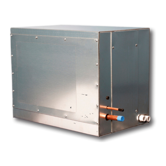
to be done at the fan coil. For charging and brazing, remove the
front access panel of the RPM-E (Fig. RPM-06). With the access
panel removed, the coil assembly will be accessible. Wet rag the
liquid and suction line (or use a heat dissipating paste) to ensure
no overheating occurs to the pre-piped coil assembly. Excess heat
may damage the RPM-E components.
Fig. RPM-06 - Remove Front Access Panel
www.hi-velocity.com
Once the system has been brazed it must be pressure tested.
Pressure testing must be done with nitrogen and not refrigerant.
Typically, pressures are tested to the maximum operating pressure
that the system will see. Allow the system to hold the nitrogen
charge for at least 15 minutes to ensure there are no leaks. Check
with local codes for proper testing procedures.
After the piping is installed and all components have been
brazed together, a vacuum pump must be used to evacuate the
system from both the low and high side to 1500 microns (200
pa). Add pressure to the system to bring the pressure above zero
psig. After allowing the refrigerant to absorb moisture, repeat the
above procedure. Evacuate the system to 500 microns (67 pa) on
the second evacuation, and ensure that the system holds at the
vacuum pressure. If not, check for leaks and evacuate again. At
this point open service valves on pre-charged condensing units,
and add refrigerant to the system if necessary.
The use of an electronic leak detector is recommended, as it is
more sensitive to small leaks under the low pressures.
Once the system has been determined clean and ready for
charging, refrigerant can be added. The service valves on the
condenser must be open at this point. Never leave the system
unattended when charging. With the system running, slowly
add refrigerant. The typical operating point of an RPM-E coil is
that of a saturated suction temperature of 38-40°F (3-4°C) and a
suction line temperature of 42-44°F (6-7°C). In order to prevent
overcharging during this stage, refrigerant should be added in
steps. This will allow time for the system to settle and prevent
'overshooting' the ideal charge. Condenser pressures and
temperatures remain similar to those in a conventional forced air
system. It is recommended that the coil be charged on a high load
day at the compressor's highest speed.
Most system start ups require only an adjustment to the
refrigerant level of the system. Should further refinement be
required, the TXV may be adjusted. A clockwise turn of the
superheat valve (the direction in which the cap is screwed on) will
result in a closing of the valve while a counterclockwise turn (the
direction in which the cap was unscrewed) will result in opening
of the valve. Always note system conditions before adjusting the
valve and allow 5 minutes for the system to settle before making
any further adjustments. Never adjust the TXV more than one
quarter turn at a time.
-4-
-4-
Module RPM-E
Refrigerant Module Installation
Evacuating
Charging
© 1995-2020 Energy Saving Products Ltd.
© 1995-2020 Energy Saving Products Ltd.