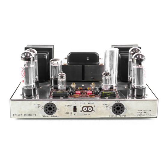
DYNACO Stereo 70 Manuale di restauro - Pagina 6
Sfoglia online o scarica il pdf Manuale di restauro per Amplificatore DYNACO Stereo 70. DYNACO Stereo 70 20. Series ii tube amplifier
Anche per DYNACO Stereo 70: Manuale di restauro (5 pagine), Manuale d'uso (12 pagine), Istruzioni per il montaggio (16 pagine)

Page 6
place for later reuse. You may simply cut the leads on those components that are
identified as discarded. You may find that the 3 transformer leads are worn and
discolored – if this is the case, using Figure 1 and the data from the original Stereo-70
manual, be certain to label each lead for identification later. Your most valuable tools
in this section will be a clean quality soldering station and Edsyn de-soldering tool.
Let's begin with the items you will be retaining:
1) De-solder the line cord from the fuse post and power switch. Use the Edsyn
Desoldering tool to clear as much solder as possible from the connections. You
can now remove the line cord and rubber grommet. If necessary you may have to
cut and re-strip these connections for reuse.
2) De-solder the black wire from the power transformer connected to the remaining
center lug of the fuse holder. Remove and store the fuse holder.
3) De-solder the remaining black wire from the power transformer connected to the
power switch and remove the power switch. Remove the power switch for reuse.
4) De-solder the four left output transformer wires (yellow, orange, brown, black)
from the left speaker connector. De-solder the remaining black wires connected to
the outer terminals of the left speaker connector. Clean and remove the speaker
connector for reuse.
5) Repeat step 4 for the right speaker connector.
6) On terminal #1 (no symbol) of the Quad electrolytic capacitor de-solder the two
red wires going to the output transformers and the one choke lead.
7) On terminal #2 (round symbol) of the Quad electrolytic capacitor disconnect the
other choke lead. You may cut the remaining wire connected to this lug that
connects to pin 8 of the rectifier tube.
8) Cut the two remaining wires connected to the terminals #3 (square symbol) and
#4 (triangle symbol) of the quad electrolytic capacitor (they connect to the
Dynaco pc board). The resistors connected to these terminals may remain. Finally,
de-solder and remove all of the wires connected to the ground lugs of the quad
electrolytic capacitor. Depending upon how your amplifier was originally
assembled, it is possible that the mounting lugs have been soldered to the chassis.
If this is the case, you should thoroughly heat each lug until the solder freely
flows and then while molten use the Edsyn solder sucker to remove all of the
solder. It may be necessary to re-apply new solder and repeat this in order to
thoroughly clean the solder. After you have removed all of the solder on the
mounting lugs, use gas pliers to rotate each lug so that its surface is perpendicular
to a line radiating from the center of the quad cap to remove the capacitor. If you
are planning on keeping the original appearance of your Stereo-70 you should
retain this capacitor - otherwise it may be discarded.
9) Carefully de-solder the three terminals (five wires) connected to the left bias
potentiometer (immediately to the left of the original selenium rectifier). Be sure
to clean all of the wire and solder remnants from this control. Remove and store
the potentiometer.
10) Repeat step 9 for the right bias potentiometer.
Dynaco Stereo 70 Power Amplifier
Restoration Manual
Detailed Procedure & Guide
R0 4-03
6
