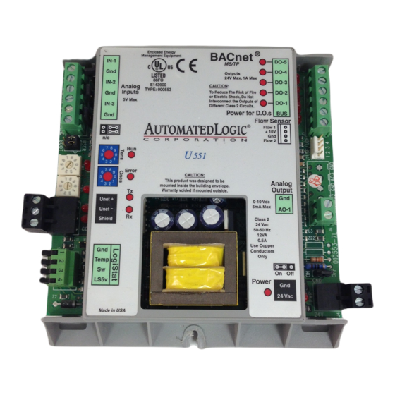
Automated Logic U551 Istruzioni tecniche - Pagina 9
Sfoglia online o scarica il pdf Istruzioni tecniche per Controllore Automated Logic U551. Automated Logic U551 11.

U module
Parameter page in SuperVision. Refer to one
of the UNI technical instructions documents
for details.
If you use a flow sensor with the U551, use
the Airflow microblock in the U551's GFB.
To connect the sensor, make sure the U551's
power is off first. Attach the total or high
pressure line from the VAV box to the
module's HI side, and attach the static
pressure line to the module's LO side.
Connect the USF to the U551 as shown in
Figure 11.
To ensure an accurate reading from the flow
sensor, use the Airflow microblock in the
module's GFB. You must calibrate this
microblock using the instructions on the FB's
Properties page in WebCTRL or Parameter
page in SuperVision. Refer to the Eikon for
WebCTRL Microblock Reference Guide or the
Eikon Microblock Reference Guide for more
information.
Revised 8/14/02 • U551
Maximum Cable Length 4 ft.
Use 20 Gauge Wire
or ALC cable (part no. 235012)
4"
10.2 cm
TOTAL
PRESSURE
NOTE: When making a sensor cable, disregard the
numbers imprinted on the plastic connector.
Figure 11. Using the UDF
9
2.5"
6.4 cm
4321
High
Low
Flow #1
STATIC
PRESSURE
High
Low
Flow #2
6"
15.2 cm
NOTE When installing the UDF, be sure to
permanently remove the W4 jumper as
shown in Figure 12 prior to performing test
and balance.
Remove
W4 jumper
BOOT
Figure 12. Removing the W4 Jumper
Writing GFBs for the U55 1
Depending on whether you are using a
WebCTRL or a SuperVision system, you must
use either Eikon for WebCTRL or Eikon 3.0a
or later to create GFBs for the U551. Be sure
© 2002 Automated Logic Corporation
IN-1
W2
Gnd
IN-2
W3
Gnd
IN-3
W4
Gnd
