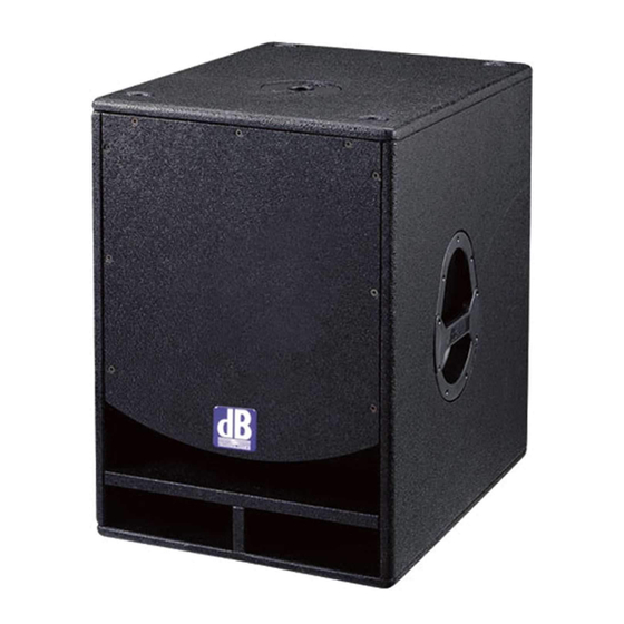
dB Technologies OPERA SUB 15 Manuale d'uso - Pagina 5
Sfoglia online o scarica il pdf Manuale d'uso per Subwoofer dB Technologies OPERA SUB 15. dB Technologies OPERA SUB 15 12.

Also featured is a circuit that controls the temperature of the toroidal transformer and
protects this against even the most exasperated operating conditions. If this cutout trips,
then the equipment is being used at the limits of its characteristics.
Such tripping is indicated by the fast flashing of the "STATUS" indicator light and by the
"mute" status audio signal (see diagnostics table).
All functions restart automatically when normal operating temperature is achieved.
Restart times can be fairly long, especially when the thermal cutout of the transformer
trips because the core takes a long time to dissipate the accumulated heat.
CC/DC/RFI
The amplifier features a short-circuit cutout for each output. This cutout places the output
signal of the stage involved in "mute".
The amplifier features relays on the audio outputs. These devices protect the speakers in
case of direct current, radio disturbances, subsonic frequencies and have an anti-bump
function at amplifier switch-on.
Tripping of these cutouts is indicated by the "POWER" indicator light going off and by the
different flashing sequences of the "STATUS" indicator light (see diagnostics table).
The amplifier will start operating normally again when the cutout condition is eliminated.
Power voltage
The amplifier features a circuit that ensures correct speaker operation in case the mains
power voltage is too high.
If the power voltage exceeds a max pre-established value (+15%) for a short time (power
peak), the fault will be indicated by means of the "POWER" indicator light, which will flash
quickly for about 10 seconds (see diagnostics table).
If the power voltage stabilizes at high levels, the amplifier will become disabled.
If the power voltage drops below the minimum established value (about -20%), the fault
will be indicated by means of the "POWER" indicator light which will start flashing slowly
(see diagnostics table).
This function is also useful in case of inadequate power supply wiring.
DIAGNOSTICS TABLE
MODULE STATUS
Power ON
Normal use
Mains power voltage
too low
too high
Temperature too high
Amplifier
Transforme
r
S
ection amplifier
In short circuit CC
Direct current DC
Does not work properly Off
"POWER"
INDICATOR LIGHT
(green)
On
On
Slow flashing
Fast flashing
On
On
Off
Off
"STATUS"
INDICATOR LIGHT
(yellow)
On for 5 sec.
Off
Off
Off
Slow flashing
Fast flashing
1 flash + 1 pause
1 flash + 1 pause
1 fla h + 1 pause
s
AUDIO
FUN TIONS
C
In mute for 5 sec.
Complete
Complete
Disengaged
In mute
In mute
In mute
In mute
In mute
10
