Autonics ADS-SE Manuale - Pagina 4
Sfoglia online o scarica il pdf Manuale per Accessories Autonics ADS-SE. Autonics ADS-SE 6. Door side sensor
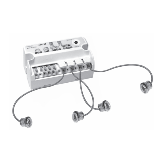
Installation
Controller installation
• Fix controller with the bolts (M4×20, 2pcs). Process the
fixing hole of controller by M4 included in the package.
Refer to dimension for installation.
Wiring connection
1. Follow as below when adjusting wiring length.
1) Cut off the wiring length as much as user needs.
2) Connect the wire to the terminal after taking off the
wire covering. It is easy to connect if soldering the end
of the wires.
2. Match wires in the number of terminals and
connect them.
①
②
Output (N.O.) (N.C.)
Emitter
Power (12-24VAC/DC)
(gray)
● Connection method for sensor
• Put outer shield and inner covered wires at once,
pressing the insert button, then take off from the button.
● Connection method for power and output wires
• Put the wires pressing the terminal ends by a driver etc.
•
Allowable diameter of power and output wires
- Single wire: Ø0.12 to 1.6mm² (AWG26 to 16)
- Stranded wire: Ø0.13 to 1.5mm² (AWG26 to 16)
17mm
Outer shield wire
Inner covered wire
9mm
①
②
※ This is non-polarity
Receiver
(blue)
type.
Door Side Sensor
Warning
When fixing controller
• Do not screw the bolts too tightly.
The fixing hole of controller may be broken.
Warning
It may cause electric shock.
• Be sure of connecting wires in power off.
Caution
It may cause damage to this product.
• Follow the left picture when cutting off the wires of
sensor head. If the cover of wire is taken off too much,
it may cause damage to this product as the end of both
wires is shorted.
Caution
Do not extend the wire of sensor head.
• Do not connect extended wire to the wire of sensor
head. It may cause malfunction by noise.
Caution
It may cause damage to this product.
• Do not connect two wires or more to a terminal.
Caution
Wiring connection
• It does not operate normally if the wiring is connected
conversely.
Caution
It may cause damage to this product.
• Make sure of connecting power wire to the terminal 4,
and 5. Otherwise, It may cause damage to this product.
(A)
Photoelectric
Sensors
(B)
Fiber
Optic
Sensors
(C)
Door/Area
Sensors
(D)
Proximity
Sensors
(E)
Pressure
Sensors
(F)
Rotary
Encoders
(G)
Connectors/
Connector Cables/
Sensor Distribution
Boxes/ Sockets
(H)
Temperature
Controllers
(I)
SSRs / Power
Controllers
(J)
Counters
(K)
Timers
(L)
Panel
Meters
(M)
Tacho /
Speed / Pulse
Meters
(N)
Display
Units
(O)
Sensor
Controllers
(P)
Switching
Mode Power
Supplies
(Q)
Stepper Motors
& Drivers
& Controllers
(R)
Graphic/
Logic
Panels
(S)
Field
Network
Devices
(T)
Software
C-13