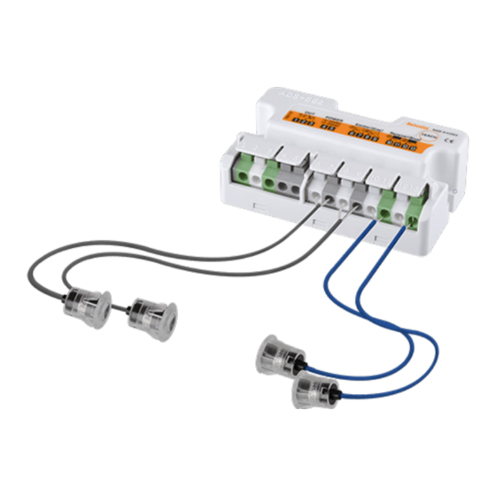
Autonics ADS-SE1 Series Manuale del prodotto - Pagina 3
Sfoglia online o scarica il pdf Manuale del prodotto per Accessories Autonics ADS-SE1 Series. Autonics ADS-SE1 Series 3. Automatic door side sensors

Dimensions
• Unit: mm, For the detailed drawings, follow the Autonics website.
•
part is only for ADS-SEC2.
■ Controller (ADS-SEC□)
77
69
■ Sensor (ADS-SHP)
• One push method
150
15
1.7
Ø 2.4, 10 m
Operation Indicator
Power
Entry activation
OFF
Operation indicator
OFF
(red, green)
N.O.
OPEN
Output
contact
N.C.
CLOSE
01) It operates in the normal. None of the person or the object is in the between sensors.
02) The state after the person or object has passed.
Sensitivity Adjustment
This function helps to set the sensitivity in the situation that if the malfunction occurs
due to the lack of sensitivity, when installing this unit at first or during operation.
Depending on the sensing distance, the controller automatically sets the optimum
sensitivity for the best operation.
■ Steps of the sensitivity setting
• When pressing the sensitivity setting key below 1 sec, the sensitivity setting is
canceled and it operates as the latest setting.
• If sensitivity is not enough or the setting is not correct, this unit may have
malfunction.
Sensitivity
Press sensitivity
during pressing
setting key
setting key (TEACH)
sensitivity setting
Sensitivity
Red/green indicator
Red/green indicator
setting
cross-flashing
indicator
01)
Ready for
Statue
sensitivity setting
sensitivity setting
01) The indicator may vary depending on the channels. See the 'Sensitivity Setting Indicators.'
■ Cautions during the sensitivity setting
• Check there are obstacles between Emitter / Receiver heads.
• Check there is dirt on the head lens of Emitter / Receiver.
• Check the wires are disconnected or connected properly as the label (nameplate).
• Check the heads of Emitter/Receiver are inclined.
• Check the above items and resolve the problems and set the sensitivity again.
Troubleshooting
Malfunction
Cause
Power voltage
It is not work.
Cable cut, disconnection
Rated sensing distance
Sometimes it does
Pollution by pollutant on the
not work.
lens of Emitter/Receiver.
Rated sensing distance
There are obstacles between
The door is opened
Emitter and Receiver.
even if people do not
enter in the sensing
There are equipments generating
area.
strong noise or ratio wave (motor,
neon lamp, generator and high-
tension wire, etc).
• Screw method
15
150
11.5
2
Ø 2.4, 10 m
M10×0.75
Out of the
Enter the
Out of the
sensing area
sensing area
sensing area
01)
ON
OFF
ON
OPEN
CLOSE
OPEN
CLOSE
OPEN
CLOSE
After 1 sec.
key
Red/green indicator
all OFF
flashing at the same time
Starts
Completes
sensitivity setting
Troubleshooting
Check the power cable and adjust
power voltage.
Check wiring and terminals.
Use it in rated sensing distance.
Remove the pollutant.
Use it in rated sensing distance.
Remove obstacles.
Keep away from the equipment
generating strong noise or ratio
wave.
Unit Descriptions
6
<ADS-SEC1>
1
OUT 1 indicator
Wiring connection
4
button
Emitter/Receiver sensor
7
connector terminals
01) ADS-SEC1: 6 to 9, ADS-SEC2: 6 to 13
Sensitivity Setting Indicators
Indicator
Connected
channel
OUT1 (red)
ON
Flashing
1 CH
02)
Flashing
OFF
ON
ON
ON
2 CH
Flashing
OFF
Flashing
OFF
• For ADS-SE2, OUT 1 indicator (red) is for the receiver status set by the emitter of 1-channel
and OUT 2 indicator (green) is for the receiver status set by the emitter of 2-channel.
• If the lack of sensitivity occurs by not-matched optical axes or pollution on the lens of
emitter / receiver during self diagnostic function, for ADS-SE1, the OUT 1 indicator (red)
flashes. For ADS-SE2, the OUT indicator of the channel with the lack of received light
Completes
the process of
flashes.
the key
Indicates
Sold Separately: Mounting Bracket
operation status
• Unit: mm, For the detailed drawings, follow the Autonics website.
■ ADS-SB12 (one push method) ■ ADS-SB10 (screw method)
Ø 12.2
M4 flat head
cap screw
24
18, Bansong-ro 513Beon-gil, Haeundae-gu, Busan, Republic of Korea, 48002
www.autonics.com | +82-51-519-3232 | [email protected]
1
3
2
4
5
6
7
7
<ADS-SEC2>
2
OUT 2 indicator
3
5
Mounting hole
6
01)
Status
After setting the
OUT2 (green)
sensitivity
Sensitivity setting
OFF
success
Sensitivity setting
Flashing
failure
OFF
-
OFF
-
1, 2 CH: sensitivity
ON
setting success
1 CH: success,
Flashing
2 CH: failure
OFF
-
1 CH: failure,
ON
2 CH: success
ON
-
1, 2 CH: sensitivity
Flashing
setting failure
OFF
-
M10×0.75
M4 flat head
cap screw
Sensor body
Lens
Head
holder
Nut
Sensor head
<ADS-SHP>
Sensitivity setting key (TEACH)
Power and output connection
terminal (1 to 5)
In operation
Received light
Emitter disconnection or
sensor cable extension
Lack of sensitivity
Interrupted light
1, 2 CH: received light
2 CH: lack of sensitivity
1 CH: received light,
2 CH: interrupted light
1 CH: lack of sensitivity
1 CH: interrupted light,
2 CH: received light
1, 2 CH: lack of sensitivity
or emitter disconnection
1, 2 CH: interrupted light
24
