DBI SALA Flexiguard Manuale di istruzioni per l'utente - Pagina 10
Sfoglia online o scarica il pdf Manuale di istruzioni per l'utente per Sensori di sicurezza DBI SALA Flexiguard. DBI SALA Flexiguard 16. Jib boom fall arrest system
3.7
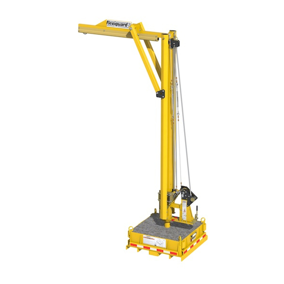
PosItIoNING tHe system: Figure 9 illustrates positioning and preparation of the Jib Boom Asembly for work. Position
and prepare the system as follows:
1. PosItIoN tHe JIb boom: Place the Jib Boom Assembly near the work area on a surface with 1° or less of slope.
slopE InDICators:
Jacks may be installed in the Leveling Jack Mounts on the Counterweight Base for purposes of leveling the Jib Boom on a surface that
is not level. Extend the Leveling Jacks until they contact the ground. Crank the Leveling Jacks up or down as needed until all Slope
Indicators indicate less than 1° of slope.
CaUtIon:
Personnel shall not be attached to the Glide Rail while the system is being raised into position.
2. rotAte tHe JIb boom: Rotate the Upright Assembly to the desired work position with the Rotation Handle.
All models except 8530571: See
Rotation Lock Pin Mechanism has pin holes at 11° increments. Reinsert the Rotation Lock Pin through the desired pin
hole to prevent the Upright Assembly from rotating out of position. Two Stop Bolts (C) can be used to limit the rotation
of the Upright Assembly.
model 8530571: See
No rotation Allowed: Rotate the Jib Boom to the desired position and then insert the Rotation Lock Pin (D)
through the inside Pin Hole (F) and aligned hole in the Rotation Plate to prevent the Jib Boom from rotating.
Limit rotation range: Insert the Rotation Lock Pin (D) through the outside Pin Hole (E) and then install Rotation
Limiters (G) on each side of the Lock Pin. Insert the Rotation Limiter mounting pegs through the desired holes in the
Rotation Plate to define the rotation range.
CaUtIon:
The Jib Boom may be used without the Rotation Lock Pin inserted, allowing 360° rotation; but can cause increased
swing fall in multiple directions in the event of a fall.
4.0
UsE
WarnInG:
Consult your doctor if there is any reason to doubt your fitness to safely absorb the shock from a fall arrest or suspension.
Age and fitness seriously affect a worker's ability to withstand falls. Pregnant women or minors must not use DBI-SALA equipment unless
in an emergency situation.
WarnInG:
Never exceed the Capacity maximums specifi ed in Table 1. Exceeding the stated capacity could collapse or tip the
system, resulting in serious injury or death.
4.1
before eAcH use: Verify that your work area and Personal Fall Arrest System (PFAS) meet all criteria defined in
Section 2 and a formal Rescue Plan is in place. Inspect the Jib Boom per the 'User' inspection points defined on the
"Inspection and Maintenance Log" (Table 2). If inspection reveals an unsafe or defective condition, do not use the Jib
Boom. Remove the system from service and contact Capital Safety regarding replacement or repair.
saFE WorK arEa:
safe working distances where the difference between the Vertical Fall Distance (F) and the Vertical Distance from the Anchorage
Connection Point (V) is less than or equal to 4 ft. (1.2 m). NEVER work at a Horizontal Distance (H) and Vertical Distance (V) that results
in a calculated Vertical Fall Distance (F) exceeding the gray shaded values on the table in Figure 3.
4.2
fALL Arrest coNNectIoNs: Figure 10 illustrates application of the Jib Boom and its Fall Arrest Connections. The
Jib Boom must always be used with a Full Body Harness and Fall Arrest subsystem. The Glide Rail System is equipped
with a Four-Wheel Trolley that travels back-and-forth inside the Rail Halves. An SRL or Energy Absorbing Lanyard can
be connected the Four-Wheel Trolley. Connect the other end of the SRL or Energy Absorbing Lanyard to the back Dorsal
D-Ring on the Harness.
WarnInG:
When transferring between SRL's, always maintain 100% tie-off to ensure fall arrest protection in the event of a fall.
Important:
No more than one person, meeting the Capacity requirements specified in Table 1, shall be attached to the Glide Four-
Wheel Trolley.
WarnInG:
Inappropriate or incompatible connections between components of the Personal Fall Arrest System (PFAS) may result in
serious injury or death. See Section 2 for details regarding connector compatibility and safe connections.
4.3
JIb rescue ANd retrIevAL kIt
Capital Safety instruction 5903369 for application and use.
The Counterweight Base is equipped with three Slope Indicators (A) for verification of a level surface. Leveling
1
in Figure 9. Remove the Rotation Lock Pin (B). The circular plate on the
2
in Figure 9.
Figure 3 illustrates the Safe Work Area for the Adjustable Jib Boom. The gray shading on the table designates
: If this kit is included with your Jib Boom Assembly (see Table 1), refer to
10