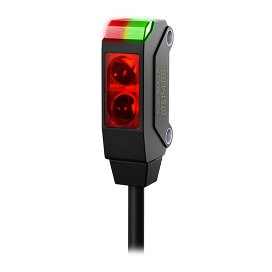
Autonics BTS1M-TDTD-P Manuale del prodotto - Pagina 2
Sfoglia online o scarica il pdf Manuale del prodotto per Accessories Autonics BTS1M-TDTD-P. Autonics BTS1M-TDTD-P 4. Photoelectric sensors

Ordering Information
This is only for reference, the actual product does not support all combinations.
For selecting the specified model, follow the Autonics website.
BTS
❶
-
❷
D
❶ Sensing distance
Number: Sensing distance (unit: mm)
Number+M: Sensing distance (unit: m)
❷ Sensing type
T: Through-beam
M: Retroreflective
L: Convergent reflective
Sold Separately
• Reflector: MS Series
• Retroreflective tape: MST Series
• Bracket B
• Slit for through-beam type: BTS1M-ST (sticker), BTS1M-ST-T (SUS material)
Cautions during Installation
• Be sure to install this product by following the usage environment, location, and
specified ratings. Consider the listed conditions below.
- Installation environment and background (reflected light)
- Sensing distance and sensing target
- Direction of target's movement
- Feature data
• When installing multiple sensors closely, it may result in malfunction due to mutual
interference.
• For installation, tighten the screw with a torque of 0.3 N m. Mount the brackets
correctly to prevent the twisting of the sensor's optical axis.
• Do not impact with a hard object or bend the cable excessively. That could decrease
the product's water resistance.
• Use this product after the test. Check whether the indicator works appropriately for
the positions of the detectable object.
Through-beam
Retroreflective
Sensor - Reflector:
At least 0.1 m apart,
Emitter - Receiver:
install to face each other
Install to face each other
(parallel with the sensing
Operation Timing Chart
■ Light ON mode
Received
light
• In Dark ON mode, the waveforms are reversed.
T
❸
-
❹
❸ Operation mode
L: Light ON
D: Dark ON
❹ Control output
No mark: NPN open collector output
P: PNP open collector output
Reflective
Sensor - Sensing target:
Install to face each other
(parallel with the sensing
side of the unit)
side of the unit)
Stable light ON area
Unstable light ON area
Unstable light OFF area
Stable light OFF area
ON
Stability indicator
OFF
(green)
ON
Operation indicator
OFF
(red)
ON
Transistor output
OFF
Connections
■ Emitter
Brown
Blue
■ Receiver, Retroreflective, Convergent reflective type
Brown
LOAD
Black
NPN
Max. 50 mA
Blue
Circuit
■ NPN open collector output
OCP
SCP
• OCP (over current protection), SCP (short circuit protection)
• If short-circuit the control output terminal or supply current over the rated specification, normal control signal is
not output due to the protection circuit.
Dimensions
• Unit: mm, For the detailed drawings, follow the Autonics website.
7.2
A
Emitter
7.2
D
C
B
A
Retroreflective
A
Optical axis of emitter
B
Optical axis of receiver
■ Reflector (MS-6)
4
Operation
level
2-Ø2.2
2
9.7
13.7
■ Sub-bracket
7
2-M2 Tap
Through-beam
12-24 VDCᜡ
Brown
Max. 50 mA
Black
PNP
12-24 VDCᜡ
LOAD
Blue
■ PNP open collector output
LOAD
OCP
SCP
Max. 50 mA
7.2
C
D
B
Receiver
C
7.2
D
B
A
Convergent reflective
C
Operation indicator (red)
D
Stability indicator (green)
■ Bracket A
10
6.2
1.4
10
4.8
2.2
7
1.2
2-M2 Tap
Reflective
12-24 VDCᜡ
Max. 50 mA
LOAD
9.5
7.7
2-Ø2.2
Ø2.5, 2m
10.8
9
2-Ø2.2
Ø2.5, 2m
1.2
1.2
