dBTechnologies VIO L1610 Manuale d'uso rapido - Pagina 2
Sfoglia online o scarica il pdf Manuale d'uso rapido per Sistema di altoparlanti dBTechnologies VIO L1610. dBTechnologies VIO L1610 7. Symmetrical active 3-way line array with coaxial driver

Thank you for choosing a dBTechnologies Product!
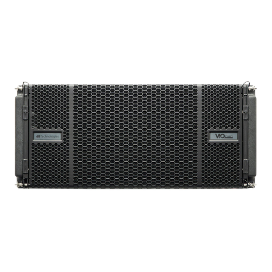
VIO L1610 is the new dBTechnologies flagship 3-way professional active line array module. It is equipped with: one
coaxial neodymium transducer (MF voice coil: 4", HF voice coil: 2,5", HF exit: 1.4") and two 10" neodymium woofers
(2.5" voice coil). The full-range acoustical design includes an efficient waveguide and a phase plug with phase
correctors, in order to reach the best coherence in line-array configuration. The mechanical design allows an easy,
accurate and quick installation in flown or stack use. The powerful
handling up to 1600 W (RMS power), is controlled by a DSP, which can perform a detailed customization of the
output sound of the speaker. In particular, thanks to the new dual rotary encoder interface, it is possible to accurately
tune the line-array configuration coverage, using the FIR filter technology. In addition, the integrated RDNET
connections are useful for a remote in-depth line-array control and configuration.
Check the site
www.dbtechnologies.com
1) Unpacking
The box contains:
N°1 VIO L1610
N°1 100-120 V FUSE
This quick start and warranty documentation
2) Easy installation
VIO L1610 can be installed in different configurations.
For a quick installation, in each side of the
loudspeakers the user can find:
Central and rear handles for easy handling (A)
- Two quick-release pin connections for frontal
mounting (B), with upper integrated front arms.
In the rear side the user can find:
- One rear bracket (C) (with movable arm) for line-
array mounting, with splay angles reference holes for
easy setup and two quick-release pins.
VIO L1610
www.dbtechnologies.com
for the complete user manual!
In order to mount the line array, for each module:
- Remove the upper front pins and lift the front arms
in the final position as shown.
- Fasten the arms with the pins in the lower holes.
- Put a second VIO L1610 and remove the lower
frontal pins.
- Put this second enclosure on the top of the first.
- Insert the front arms in the position shown, aligning
the related holes.
2
info@dbtechnologies‐aeb.com
DIGIPRO®
G4 amplifier section, capable of
420120324Q REV.1.0
