Galaxy DX 919 Manuale d'uso - Pagina 4
Sfoglia online o scarica il pdf Manuale d'uso per Ricetrasmettitore Galaxy DX 919. Galaxy DX 919 11. Two way citizens band mobile transceiver
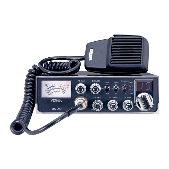
6. SWR LED: This LED lights red when your SWR is higher than about 3:1. This is
not an exact indicator of 3:1 SWR, but it is an indication that you should check
your SWR reading.
7. CHANNEL SELECTOR: This control is used to select the desired transmit and
receive channel.
8. FRONT PANEL METER: The front panel meter allows the user to monitor
incoming signal strength, RF output power, SWR level and AM modulation level.
9. RF GAIN CONTROL: This control is used to reduce the gain of the RF (receive)
amplifier under strong signal conditions.
10. DIMMER CONTROL: This knob controls the level of brightness for the meter
lamp and channel display.
11. SWR/MOD/PWR SWITCH: This switch controls the function of the meter
during the transmit mode. In the "SWR" position, the meter indicates the Standing
Wave Ratio (SWR) of your antenna. There are no adjustments because the SWR
circuit in this radio calibrates itself automatically. When the switch is in the
"MOD" position, the green scale on the meter indicates your percentage of
modulation in the AM mode only. They are most accurate when testing at
maximum power output. When this switch is in "PWR" position, the meter
indicates your power output.
12. NB-ANL/CB/PA SWITCH: When the switch is in the NB/ANL position, the
Noise Blanker (NB) and Automatic Noise Limiter (ANL) circuits are activated.
The Noise Blanker is very effective in eliminating repetitive impulse noise such
as ignition interference. In the CB position, the PA function is disabled and the
radio will transmit and receive on the speaker that is connected. In the PA position,
the radio acts as public address amplifier. Your voice will come out of the speaker
that is plugged into the PA. SP. jack on the rear panel. The radio does not operate
when you are in the PA mode.
13. TALKBACK SWITCH: This feature is used to monitor your own voice. For
example, you could use this feature to compare different microphones. HI is high
volume. LO is low volume. The Talkback circuit is off when the switch is in the
OFF position.
14. RX/TX LED: This LED is green during receive and red during transmit.
15. CHANNEL DISPLAY: The channel display indicates the current selected
channel.
- 6 -
REAR PANEL
This device complies with part 15 of the FCC Rules.
Operation is subject
to the condition that this device
does not cause harmful interference.
Service Manual at www.GalaxyRadios.com
MODEL NO. : DX 919
FCC ID : MEE − DX − 919
AM 40 CH
CB TRANSCEIVER
DATE OF MFG.:
SERIAL NO. :
1. ANTENNA: This jack accepts a 50-ohm coaxial cable with a PL-259 type plug.
2. DC POWER: This jack accepts the 13.8V DC power cable with built-in fuse.
The power cord provided with the radio has a black and red wire. The black goes
to negative and red goes to positive.
3. PA SP: This jack is for PA operation. Before operating, you must first connect a
PA speaker (8 ohms, 4W) to this jack.
4. EXT. SP: This jack accepts a 4 to 8 ohm, 5-watt external speaker. When the
external speaker is connected to this jack, the built-in speaker will be disabled.
5. F.C.: This jack is used to connect the optional Galaxy FC347 six-digit frequency
counter. All connections, including DC power, are provided to the FC347 through
this jack.
3
5
PA SP.
EXT SP.
ANT
F.C.
- DC 13.8V +
1
2
- 7 -
4