Galaxy DX 95T Manuale d'uso - Pagina 4
Sfoglia online o scarica il pdf Manuale d'uso per Ricetrasmettitore Galaxy DX 95T. Galaxy DX 95T 10. 10 meter amateur mobile transceiver with built-in frequency counter & starlite face plate
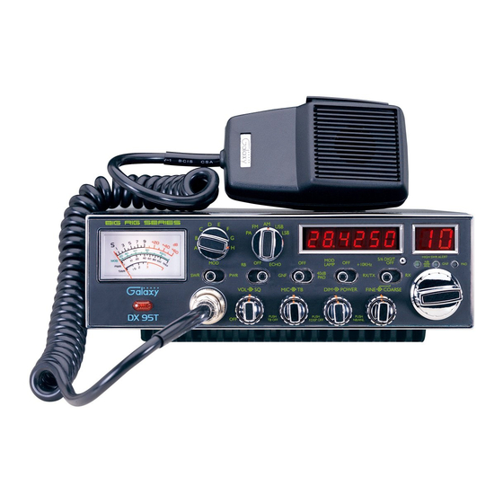
5. SQUELCH CONTROL: This knob is used to eliminate background noise being
heard through the receiver, which can be disturbing when no transmissions are
being heard through the receiver. To use this feature, turn the knob fully
counterclockwise and then turn clockwise slowly until the background noise is just
eliminated. Further clockwise rotation will increase the threshold level which a
signal must overcome in order to be heard. Only strong signals will be heard at a
maximum clockwise setting.
6. MIC GAIN CONTROL/PUSH TB OFF SWITCH: Adjusts the microphone gain
in transmit and PA modes. This controls the gain to the extent that full talk power is
available several inches away from the microphone. In the Public Address (PA)
mode, the control functions as the volume control. Pushing this knob turns the
Talkback circuit on and off.
7. TALKBACK (TB) CONTROL: Adjust this knob for desired volume of Talkback.
This is used to monitor your own voice. For example, you could use this feature to
compare different microphones.
8. DIM CONTROL/PUSH FREQUENCY DISPLAY OFF SWITCH: This knob
controls the level of brightness for the meter lamp, faceplate, frequency display and
channel display. Pushing this knob turns the Frequency Display on and off
9. RF POWER CONTROL: This control allows the user to adjust RF power output.
10. COARSE/FINE CONTROL/PUSH NB-ANL OFF SWITCH: Allows variation
of the radio operating frequencies above and below the channel frequency.
Although this control is intended primarily to tune in SSB signals, it may be used to
optimize AM/FM signals. Pushing this knob turns the Noise Blanker (NB) /
Automatic Noise Limiter (ANL) circuit on and off. The Noise Blanker (NB) is very
effective in eliminating repetitive impulse noise such as ignition interference.
11. RX/TX/OFF/RX SWITCH: When in the RX/TX position, the two clarifiers
(Coarse and Fine) function on both receive and transmit. When the switch is in the
RX position, the Fine clarifier functions on receive only and the Coarse clarifier
still functions on both receive and transmit. When in the OFF position, both
clarifiers have no effect on the frequency.
12. CHANNEL SELECTOR: This control is used to select the desired transmit and
receive channel.
13. GNF LED: This LED lights green when the GNF function is on.
6
14. FRONT PANEL METER: The front panel meter allows the user to monitor
incoming signal strength, RF output power, SWR level and AM modulation level.
15. ILLUMINATED FACE PLATE: All faceplate lettering will fully illuminate to
allow the user easy viewing at night. This unique, solid state, backlight is designed
to maximize night vision while minimizing eye fatigue. Therefore, it is ideal for
switch and control recognition day or night.
16. BAND SELECTOR: This switch is used to select the band.
17. RB/OFF/ECHO SWITCH: When in the RB position, the radio transmits an audio
tone at the end of your transmission to indicates that transmission has ended. As a
courtesy to others, use the Roger Beep only when necessary. When the switch is in
the ECHO position it turns the Echo circuit on. The time and amount of Echo effect
are preset at the factory. There are no external controls for these adjustments.
However, there are two small internal adjusting pots inside the Echo module, which
is located in a metal box just behind the channel selector switch. These adjusting
pots are labeled Echo and Time.
18. MODE SWITCH: This control allows you to select one of the following operating
modes: PA/FM/AM/USB/LSB.
19. GNF/OFF/40dB PAD SWITCH: When in the GNF position, the Galaxy Noise
Filter is activated. This is a special noise filter that de-emphasizes audio high
frequency response in order to increase the signal-to-noise ratio of weak signals.
While you will notice a dramatic reduction in the "rushing" sound when this filter
is activated, it does not have much effect on the signal-to-noise ratio of strong
signals. The GNF is for SSB use only and will cause distortion if used during AM
reception. When the switch is in the 40dB PAD position, the 40dB attenuation
circuit is activated. When the switch is in the OFF position, neither the GNF circuit
nor the Attenuation circuit will be active.
20. MOD LAMP/OFF/+10KHz SWITCH: When in the MOD LAMP position, the
Mod Lamp circuit is activated. When the switch is in the +10KHz position, the
frequency is shifted up 10KHz.
21. FREQUENCY COUNTER: This display indicates the frequency of the selected
channel.
22. 5/6 DIGIT SWITCH: Pushing this switch will change the frequency display from
a six digit readout to a five digit readout. It will turn the hundreds digit on and off.
Then a frequency of 28.3056 MHz would read 28.305 MHz.
7