Autonics ARD-DI08A Manuale - Pagina 3
Sfoglia online o scarica il pdf Manuale per Sistemi I/O Autonics ARD-DI08A. Autonics ARD-DI08A 8. Devicenet digital remote i/o
Anche per Autonics ARD-DI08A: Manuale (8 pagine)

ARD-D Series
DeviceNet Communication
Item
Communication
Communication distance
NODE ADDRESS setting
Communication speed
Insulation
DeviceNet power
Approval
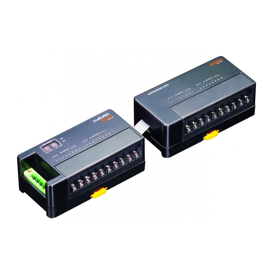
Unit Description
Basic unit
● Standard terminal block type
2
3
1
7
● Sensor connector type
2
9
8
Expansion unit
● Standard terminal block type
1
● Sensor connector type
C-144
Specifications
I/O Slave messaging(Group 2 Only slave)
·Poll command: Yes ·Bit_strobe command: Yes ·Cyclic command: Yes ·COS command: Yes
Max. 500m(125kbps), Max. 250m(250kbps), Max. 100m(500kbps)
Max. 64 nodes(set by the front rotary switch)
125, 250, 500kbps(automatically set when connecting with Master)
I/O and inner circuit: Photocoupler isolated, DeviceNet and inner circuit: non-insulation,
DeviceNet power: non-isolated
·Rated voltage: 24VDC ·Voltage range: 12-28VDC ·Power consumption: Max. 3W
ODVA Conformance tested
4
5
6
3
6
5
4
1
3
2
4
5
3
4
7
1
2
6
1. DeviceNet connector
No.
Color For
Organization
5
Red
24VDC(+)
4
White CAN_H
3
None Shield
2
Blue
CAN_L
1
Black 24VDC(-)
2. Rotary switch for node address
: Rotary switch for setting node address.
×10 represents tens digit and ×1 represents ones digit.
3. Status LED: It displays the status of unit(MS) and network(NS).
4. I/O status LED: It displays each I/O status.
5. Rail lock: It is used for mounting DIN rail or with screw.
6. Connector output part: It connects an expansion unit.
7. I/O terminal block: It is used for connecting external device I/O.
8. Sensor connector: It is used for connecting external device I/O.
9. External power connector: It is used for supplying external power.
1. Connector input part
: It connects expansion unit and is joined into
expansion connector output.
2. I/O status LED: It displays each I/O status.
3. Rail lock: It is used for mounting DIN rail or with screw.
4. Connector output part: It connects an expansion unit.
5. I/O terminal block: It is used for connecting external device I/O.
6. Sensor connector: It is used for connecting external device I/O.
7. External power connector: It is used for supplying external power
V+
CAN_H
SHIELD
CAN_L
V-
