9dot SPP Manuale - Pagina 13
Sfoglia online o scarica il pdf Manuale per Apparecchiature di laboratorio 9dot SPP. 9dot SPP 15.
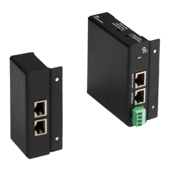
SPI Output power supply
The main function of the PoE injector of this device is to allow the powering of other equipment on the network. SPI PoE
injector modules are passive injectors.
IMPORTANT NOTE: Unlike active PoE, passive PoE does not use any protocol to determine the type of device to be powered;
it simply applies a type of voltage to its port without identifying which type of PoE standard or supply voltage the connected
load is compatible with. Using an unsuitable voltage and / or wrong pin out can cause irreparable damage to the powered
device.
It is possible to power a wide range of devices that accept different voltages as this module essentially replicates the voltage
from the power terminals to the PoE output ports without applying any conversion.
This offers great versatility when it comes to connecting several PoE devices in the same infrastructure as each module can be
powered with a different voltage than the rest.
In addition to supporting different voltages, the SPI has the ability to select the pin out of the PoE output ports, with two
selectors placed on the side of the module, thus allowing it to power a wide range of devices on the market.
To find out if your PoE device can be powered by SPI, just check the pin out that the switches allow you to select and see if it
matches the input pin out of your equipment
Selectors
With the mode and polarity selectors of the SPI module it is possible to select the output pin out of the PoE port, according to
the following tables:
Special case -48V
There are installations that require -48V mains power supply, this option is perfectly feasible with SPI. We simply have to
connect the -48V to the SPI input
on the input pin out of the devices we want to connect.
Protection
On the PoE port there are double phase surge arresters TVS (Transient Voltage Suppression) and GDT (Gas Discharge Tube).
See the sections "Selectors"
3
As explained in the "Input power supply" section
4
SPI & SPP MANUAL
.
3
Modality
MODE A+B
MODE B
MODE A
Table 4 - SPI selectable mode types
Polarity
NORMALE
+ 4,5 and/or 1,2 | – 7,8 and/or 3,6
INVERSA
– 4,5 and/or 1,2 | + 7,8 and/or 3,6
Table 5 - SPI selectable polarity types
and then select the correct mode and polarity in order to get -48V on the PoE ports based
4
Pins
Po4P
4,5 / 7,8
1,2 / 3,6
Pins
13
VER. 2 REV. 0